Color Signal Description
White AI2 / RS485+ Analog in 2 or RS485+
Brown AI3 / RS485- Analog in 3 or RS485-
Access Tool I/O in the Installation Tab (see partPart II PolyScope Manualon page97) to
set the internal power supply to 0V, 12V or 24V. The electrical specifications are shown
below:
Parameter Min Typ Max Unit
Supply voltage in 24V mode 23.5 24 24.8 V
Supply voltage in 12V mode 11.5 12 12.5 V
Supply current (single pin)* - 1000 2000** mA
Supply current (dual pin)* - 1500 2000** mA
Supply capacitive load - - 8000*** uF
*It is highly recommended to use a protective diode for inductive loads.
**Peak for max 1 second, duty cycle max:10%. Average current over 10 seconds must not
exceed typical current.
***When tool power is enabled, a 400ms soft start time begins allowing a capacitive load
of 8000uF to be connected to the tool power supply at startup. Hot-plugging the
capacitive load is not allowed.
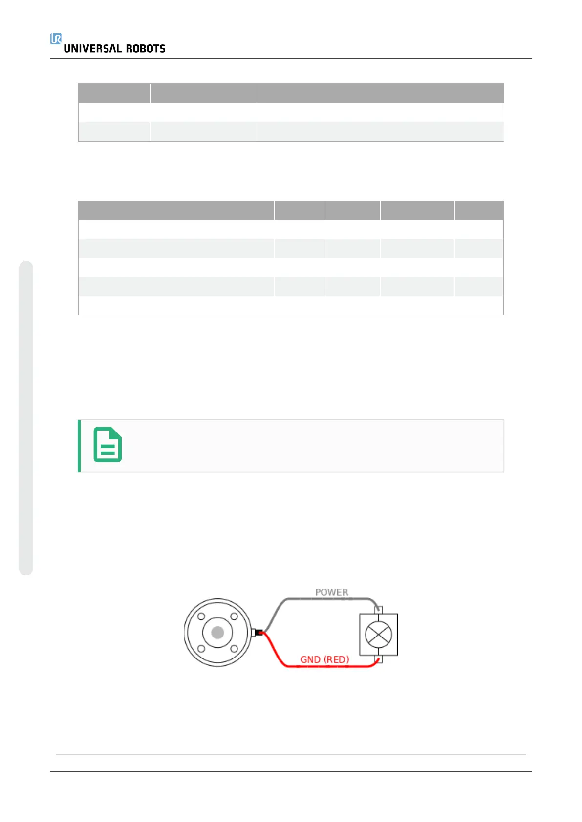
NOTE
The tool flange is connected to GND (same as the red wire).
6.8.1. Tool Power Supply
6.8.2. Power Supply
Access Tool I/O in the Installation Tab (see partPart II PolyScope Manualon page97) to
set the internal power supply to 0V, 12V or 24V.
6.8.3. Dual Pin Power Supply
In Dual Pin Power mode, the output current can be increased as listed in (6.8. Tool I/Oon
the previous page table two).
UR5e 50 User Manual
6.Electrical Interface
Copyright © 2009–2021 by UniversalRobotsA/S. All rights reserved.

 Loading...


