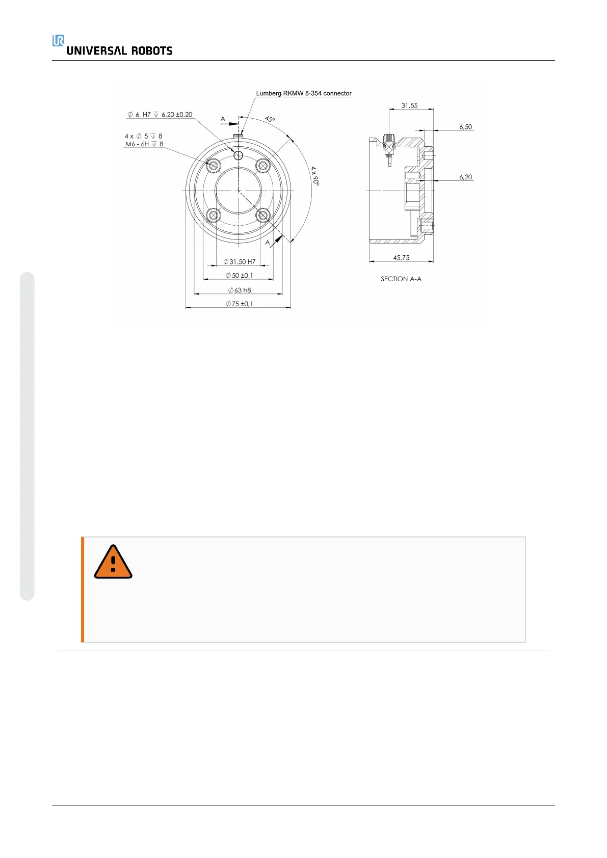
6.2:The tool output flange (ISO 9409-1-50-4-M6) is where the tool is mounted at the tip
of the robot. All measures are in mm.
Control Box
The Control Box can be hung on a wall or placed on the ground. A clearance of 50mm on
each side of the Control Box is needed for sufficient airflow.
Teach Pendant
The Teach Pendant can be hung on a wall or on the Control Box. Verify that the cable
does not cause tripping hazard.
You can buy extra brackets for mounting the Control Box and Teach Pendant.
WARNING
1. Make sure the Control Box, Teach Pendant and cables do not come
into contact with liquids. A wet Control Box could cause fatal injury.
2. Place the Teach Pendant (IP54) and Control Box (IP44) in an
environment suited for the IP rating.
5.4. Maximum Payload
The rated payload of the Robot Arm depends on the center of gravity offset of the payload, see
Figure 6.3.
The center of gravity offset is defined as the distance from the center of the tool flange to the
center of gravity of the attached payload.
UR5e 30 User Manual
5.Mechanical Interface
Copyright © 2009–2021 by UniversalRobotsA/S. All rights reserved.

 Loading...


