CAUTION
The Digital Outputs in the tool are not current-limited. Overriding the
specified data can cause permanent damage.
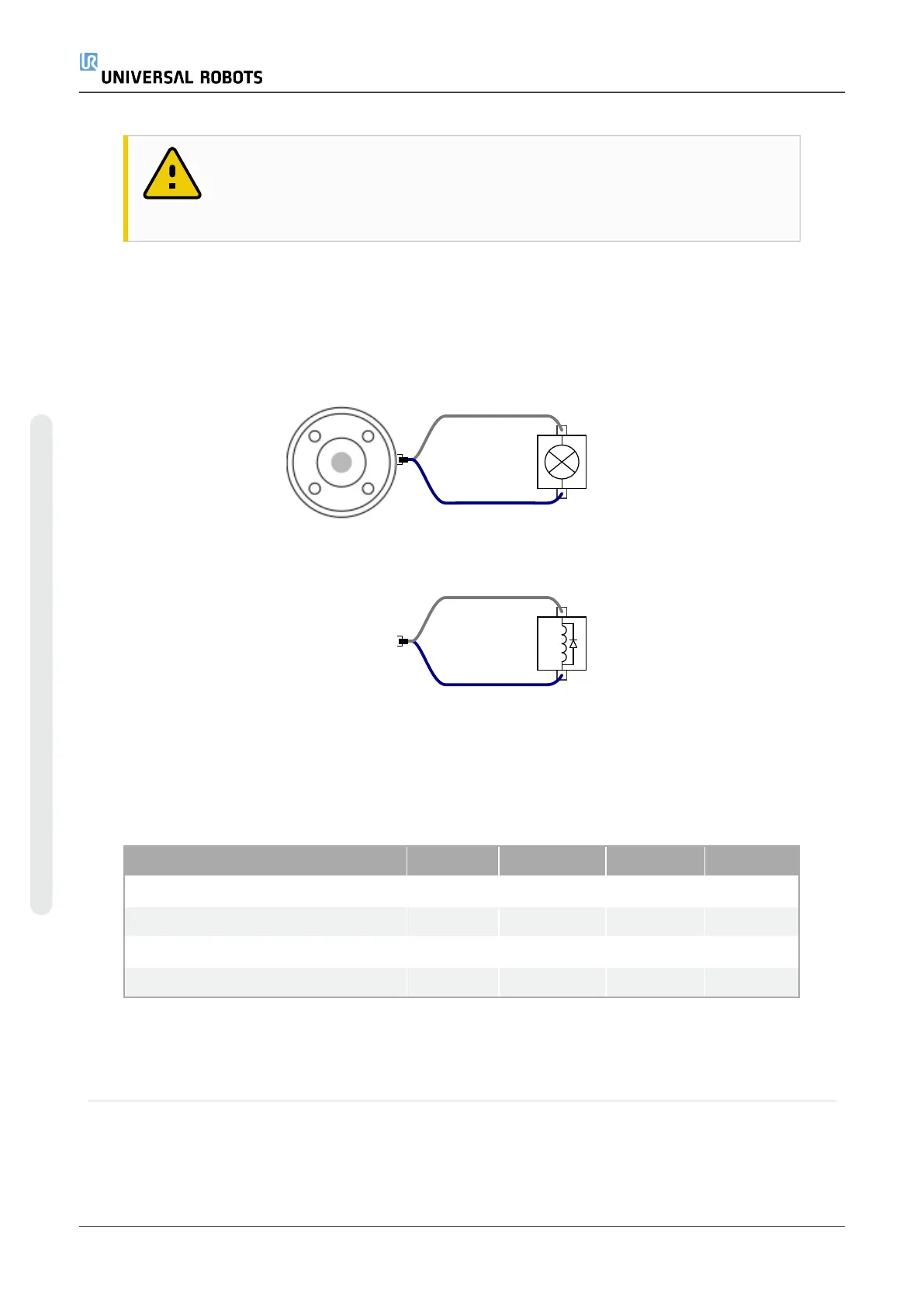
Using Tool Digital Outputs
This example illustrates turning on a load using the internal 12V or 24V power supply. The
output voltage at the I/O tab must be define. There is voltage between the POWER
connection and the shield/ground, even when the load is turned off.
It is recommended to use a protective diode for inductive loads, as shown below.
6.8.5. Tool Digital Inputs
The Digital Inputs are implemented as PNP with weak pull-down resistors. This means
that a floating input always reads as low. The electrical specifications are shown below.
Parameter Min Type Max Unit
Input voltage -0.5 - 26 V
Logical low voltage - - 2.0 V
Logical high voltage 5.5 - - V
Input resistance - 47k - Ω
Using the Tool Digital Inputs
This example illustrates connecting a simple button.
UR5e 52 User Manual
6.Electrical Interface
Copyright © 2009–2021 by UniversalRobotsA/S. All rights reserved.

 Loading...


