1. In the Header, tap Installation.
2. In the list on the left, tap General.
3. Tap Tool IO and select Dual Pin Power.
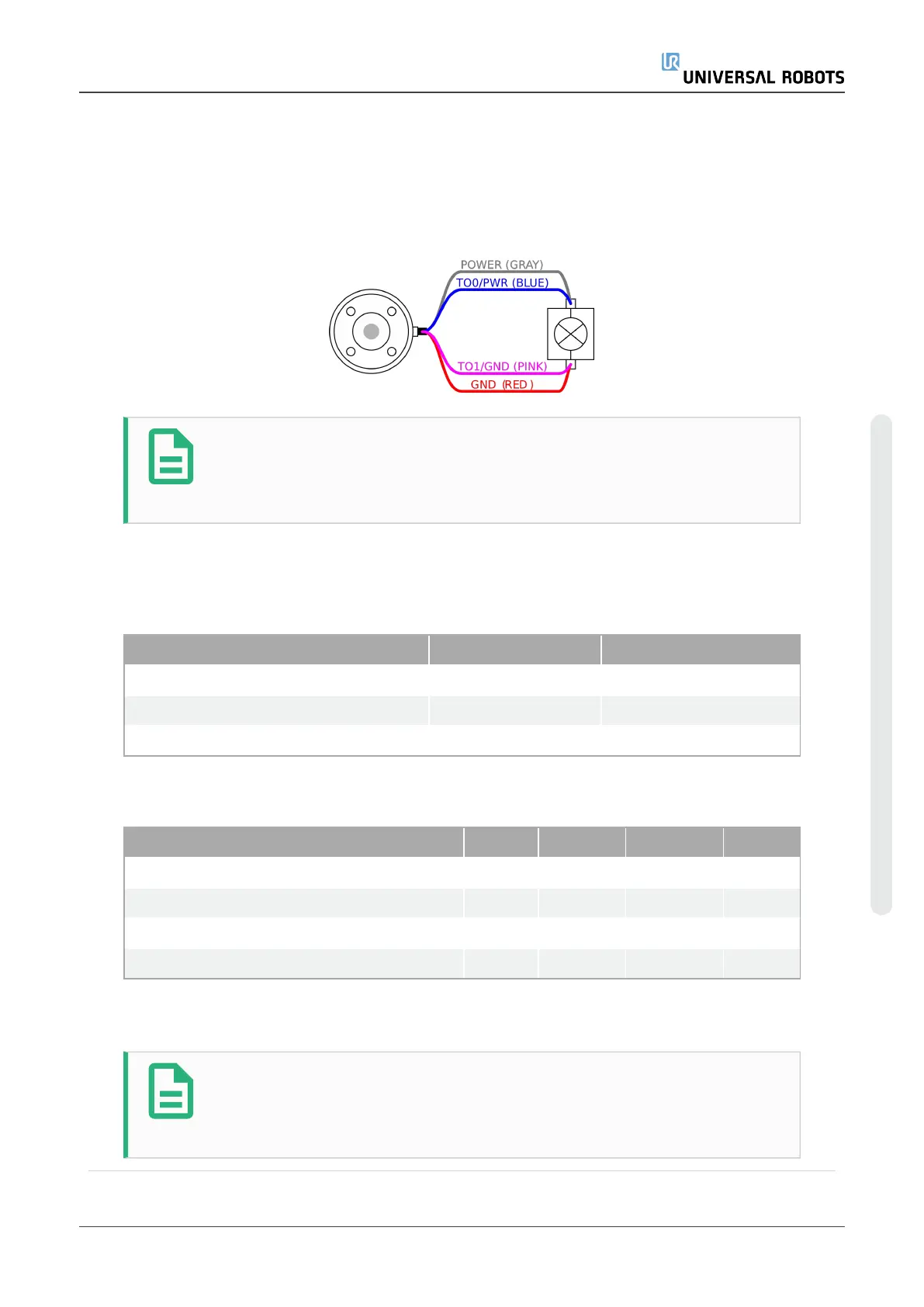
4. Connect the wires Power (gray) to TO0 (blue) and Ground (red) to TO1 (pink).
NOTE
Once the robot makes an Emergency Stop, the voltage is set to 0V for
both Power Pins (power is off).
6.8.4. Tool Digital Outputs
Digital Outputs support three different modes:
Mode Active Inactive
Sinking (NPN) Low Open
Sourcing (PNP) High Open
Push / Pull High Low
Access Tool I/O in the Installation Tab (see partPart II PolyScope Manualon page97) to
configure the output mode of each pin. The electrical specifications are shown below:
Parameter Min Typ Max Unit
Voltage when open -0.5 - 26 V
Voltage when sinking 1A - 0.08 0.09 V
Current when sourcing/sinking 0 1000 1000 mA
Current through GND 0 1000 3000* mA
*Peak for max 1 second, duty cycle max: 10%. Average current over 10 seconds must not
exceed typical current.
NOTE
Once the robot makes an Emergency Stop, the Digital Outputs (DO0 and
DO1) are deactivated (High Z).
User Manual 51 UR5e
6.Electrical Interface
Copyright © 2009–2021 by UniversalRobotsA/S. All rights reserved.

 Loading...


