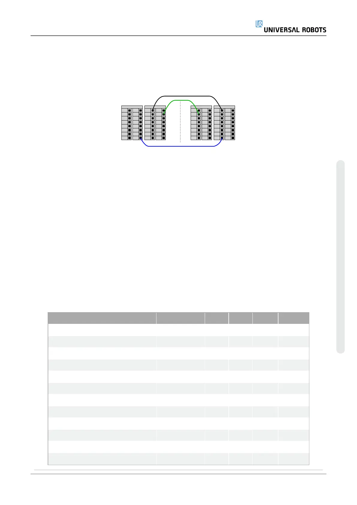
6.4.5. Communication with other machines or PLCs
You can use the digital I/O to communicate with other equipment if a common GND (0V)
is established and if the machine uses PNP technology, see below.
24V
DI1
24V
DI2
24V
DI3
24V
DI0
Digital Inputs
24V
DI5
24V
DI6
24V
DI7
24V
DI4
0V
DO1
0V
DO2
0V
DO3
0V
DO0
Digital Outputs
0V
DO5
0V
DO6
0V
DO7
0V
DO4
24V
DI1
24V
DI2
24V
DI3
24V
DI0
Digital Inputs
24V
DI5
24V
DI6
24V
DI7
24V
DI4
0V
DO1
0V
DO2
0V
DO3
0V
DO0
Digital Outputs
0V
DO5
0V
DO6
0V
DO7
0V
DO4
A B
6.4.6. General purpose analog I/O
The analog I/O interface is the green terminal. It is used to set or measure voltage (0-10V)
or current (4-20mA) to and from other equipment.
The following directions is recommended to achieve the highest accuracy.
•
Use the AG terminal closest to the I/O. The pair share a common mode filter.
•
Use the same GND (0V) for equipment and Control Box. The analog I/O is not
galvanically isolated from the Control Box.
•
Use a shielded cable or twisted pairs. Connect the shield to the GND terminal at the
terminal called Power.
•
Use equipment that works in current mode. Current signals are less sensitive to
interferences.
In the GUI you can select input modes (see partPart II PolyScope Manualon page97).
The electrical specifications are shown below.
Terminals Parameter Min Typ Max Unit
Analog Input in current mode
[AIx - AG]
Current 4 - 20 mA
[AIx - AG]
Resistance - 20 - ohm
[AIx - AG]
Resolution - 12 - bit
Analog Input in voltage mode
[AIx - AG]
Voltage 0 - 10 V
[AIx - AG]
Resistance - 10 - Kohm
[AIx - AG]
Resolution - 12 - bit
Analog Output in current mode
[AOx - AG]
Current 4 - 20 mA
[AOx - AG]
Voltage 0 - 24 V
[AOx - AG]
Resolution - 12 - bit
User Manual 43 UR5e
6.Electrical Interface
Copyright © 2009–2021 by UniversalRobotsA/S. All rights reserved.

 Loading...


