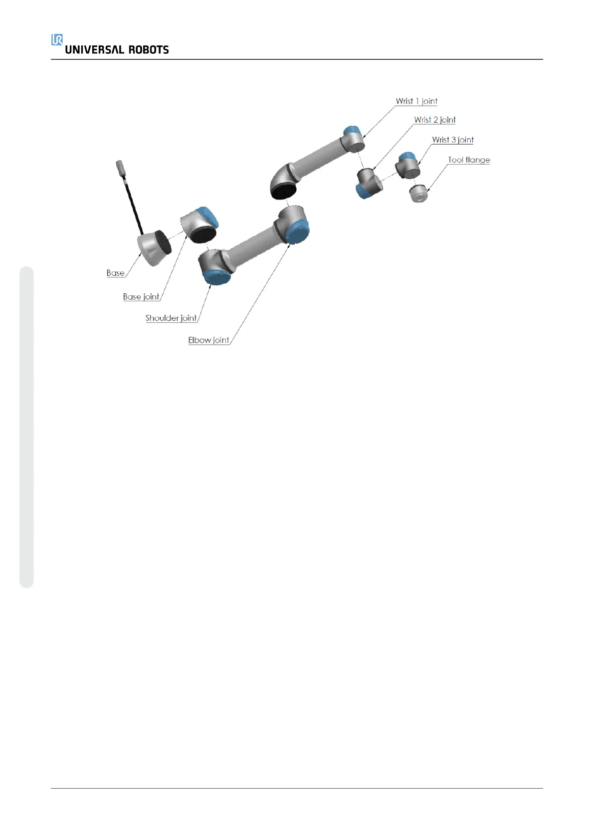
2.1:The joints, the base and the tool flange of the Robot Arm.
With six joints and a wide scope of flexibility, Universal Robots e-Series collaborative robot arms
are designed to mimic the range of motion of a human arm. Using our patented programming
interface, PolyScope, it is easy to program the robot to move tools and communicate with other
machines using electrical signals. Figure 2.1:The joints, the base and the tool flange of the Robot
Arm.above illustrates the main components of the robot arm and can be used as a reference
throughout the manual.
1.1. What Do the Boxes Contain
When you order a robot, you receive two boxes. One contains the Robot Arm, the other contains:
•
Control Box with Teach Pendant
•
Mounting bracket for the Control Box
•
Mounting bracket for the Teach Pendant
•
Key for opening the Control Box
•
Cable for connecting the robot arm and the Control Box (see options in 15.Technical
Specificationson page83)
•
Mains cable or Power cable compatible to your region
•
This manual
UR5e 2 User Manual
1.Preface
Copyright © 2009–2021 by UniversalRobotsA/S. All rights reserved.

 Loading...


