6.Electrical Interface
6.1. Introduction
This chapter describes electrical interface groups for the Robot Arm in the Control Box. Examples
are given for most types of I/O. The term I/O refers to both digital and analog control signals to or
from the electrical interface groups listed below.
•
Mains connection
•
Robot connection
•
Controller I/O
•
Tool I/O
•
Ethernet
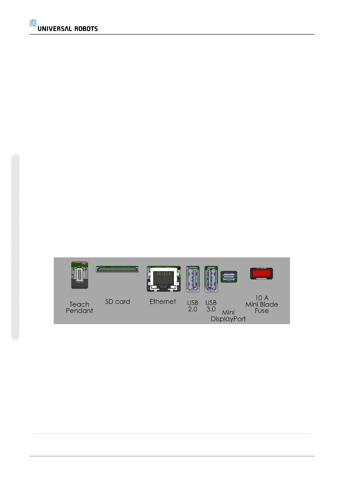
6.1.1. Control Box Bracket
On the underside of the I/O interface groups, there is a bracket with ports that allows for additional
connections (illustrated below). The base of the Control Box has a capped opening for easy
connection (see 6.Electrical Interfaceabove).
The Mini Displayport supports monitors with Displayport and requires an active Mini Display to DVI
or HDMI converter to connect monitors with DVI/HDMI interface. Passive converters do not work
with DVI/HDMI ports.
The Fuse must be UL marked, Mini Blade type with maximum current rating: 10A and minimum
voltage rating: 32V
6.2. Ethernet
The Ethernet interface can be used for:
•
MODBUS, EtherNet/IP and PROFINET (see partPart II PolyScope Manualon
page97).
•
Remote access and control.
UR5e 32 User Manual
6.Electrical Interface
Copyright © 2009–2021 by UniversalRobotsA/S. All rights reserved.

 Loading...


