Tool Communication Interface
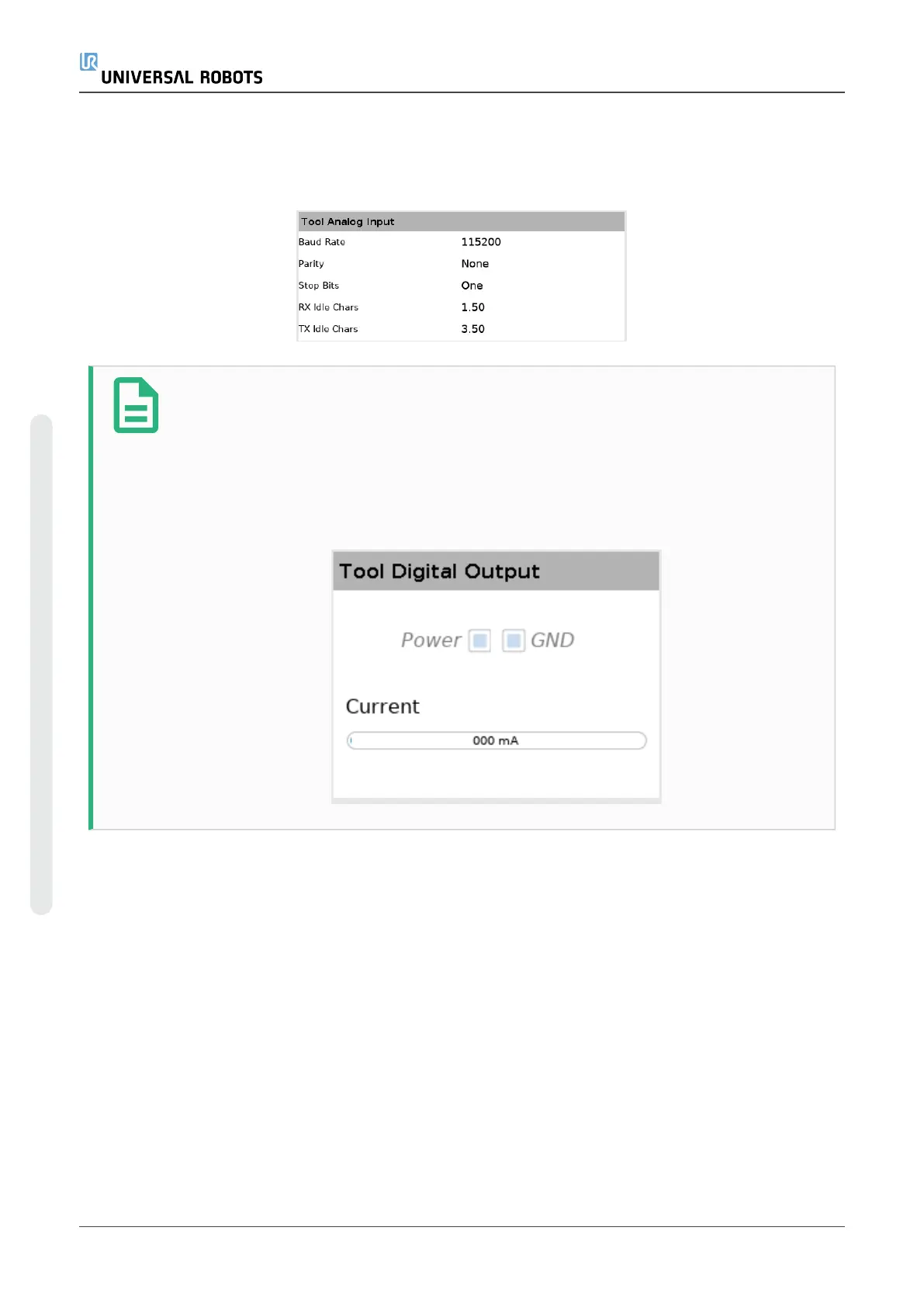
When the Tool Communication Interface TCI is enabled, the tool analog input becomes
unavailable. On the I/O screen, the Tool Input field changes as illustrated below.
NOTE
When the Dual Pin Power is enabled, the tool digital outputs must be named as
follows:
•
tool_out[0] (Power)
•
tool_out[1] (GND)
The Tool Output field is illustrated below.
26.2. MODBUS
The screenshot below displays the MODBUS client I/O signals as they are set up in the installation.
Using the drop-down menus at the top of the screen, you can change the displayed content based
on signal type and MODBUS unit if more than one is configured. Each signal in the lists contains its
connections status, value, name, and signal address. The output signals can be toggled if the
connection status and the choice for I/O tab control allows it (see ).
UR5e 246 User Manual
26.I/O Tab
Copyright © 2009–2021 by UniversalRobotsA/S. All rights reserved.

 Loading...


