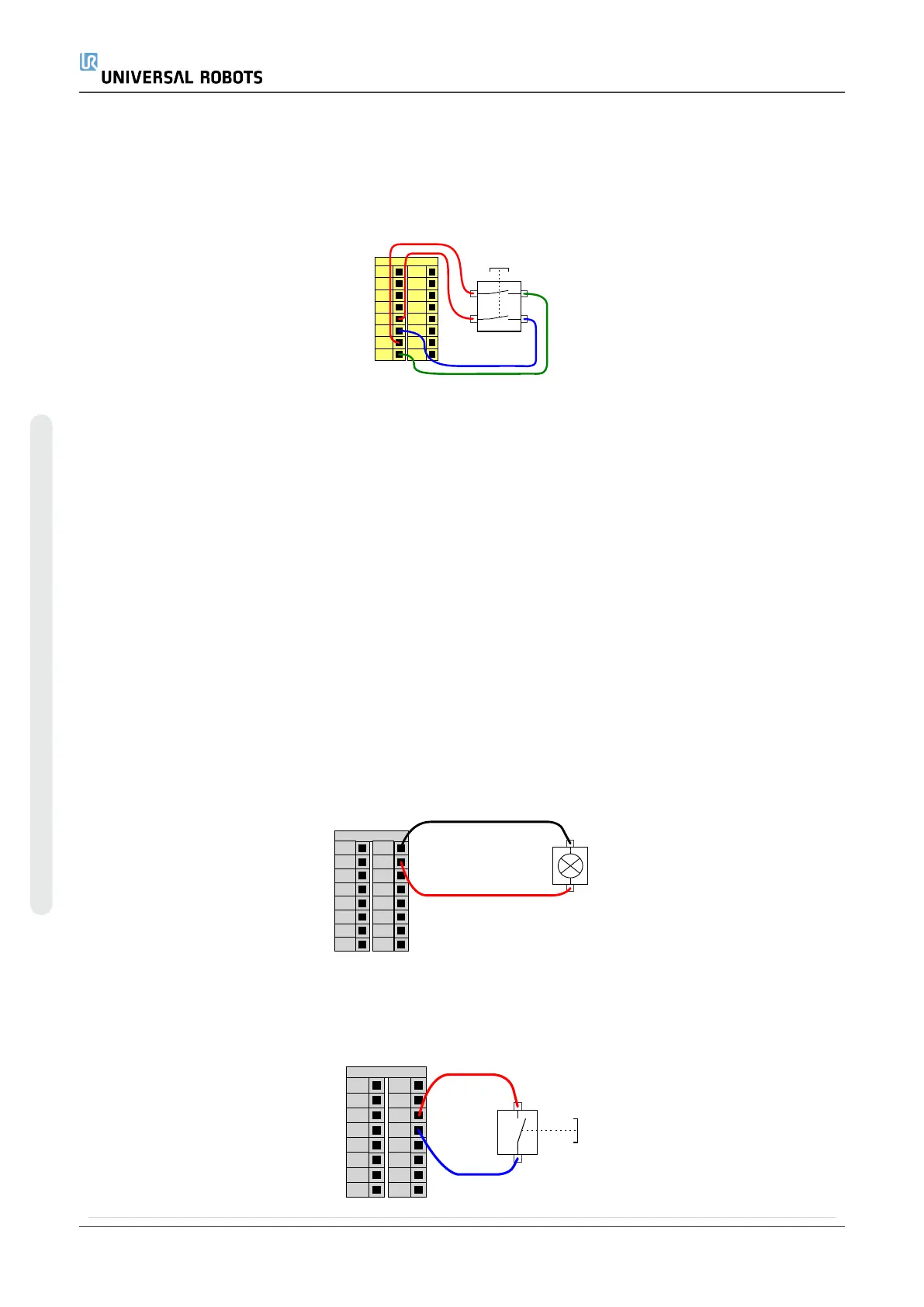
Operational Mode Switch
The illustration below shows an Operational Mode Switch. See section20.1. Operational
Modeson page115 for more about operational Modes.
24V
CI1
24V
CI2
24V
CI3
24V
CI0
24V
CI5
24V
CI6
24V
CI7
24V
CI4
Configurable Inputs
Operational mode Switch
6.4.3. General purpose digital I/O
This section describes the general purpose 24V I/O (Gray terminals) and the configurable
I/O (Yellow terminals with black text) when not configured as safety I/O. The common
specifications in section6.4.1. Common specifications for all digital I/Oon page36 must
be observed.
The general purpose I/O can be used to drive equipment like pneumatic relays directly or
for communication with other PLC systems. All Digital Outputs can be disabled
automatically when program execution is stopped, see partPart II PolyScope Manualon
page97. In this mode, the output is always low when a program is not running. Examples
are shown in the following subsections. These examples use regular Digital Outputs but
any configurable outputs could also have be used if they are not configured to perform a
safety function.
Load controlled by a Digital Outputs
This example shows how a load is controlled from a Digital Outputs when connected.
0V
DO1
0V
DO2
0V
DO3
0V
DO0
Digital Outputs
0V
DO5
0V
DO6
0V
DO7
0V
DO4
LOAD
6.4.4. Digital Inputs from a button
This example illustrates connecting a simple button to a Digital Inputs.
24V
DI1
24V
DI2
24V
DI3
24V
DI0
Digital Inputs
24V
DI5
24V
DI6
24V
DI7
24V
DI4
UR5e 42 User Manual
6.Electrical Interface
Copyright © 2009–2021 by UniversalRobotsA/S. All rights reserved.

 Loading...


