2-6
IM DLM4038-02EN
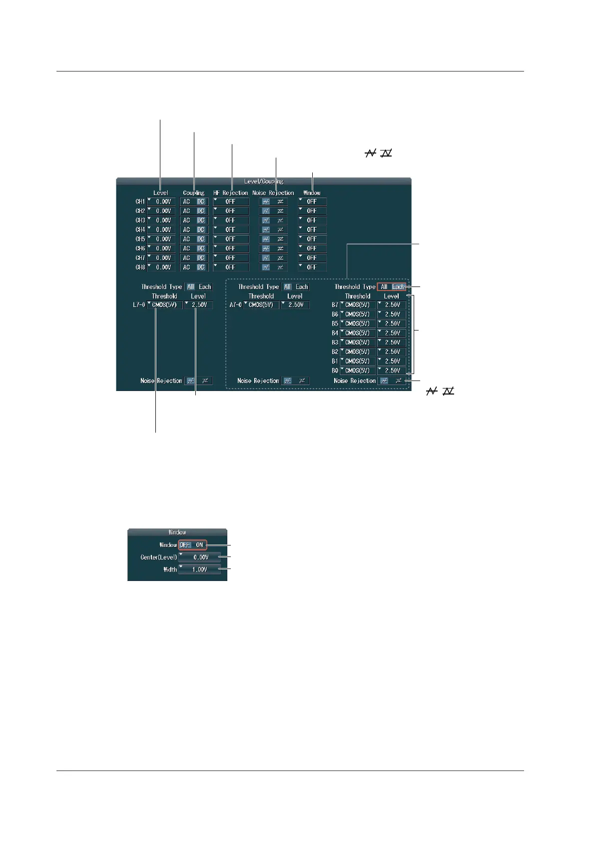
Example: When the 701989 logic probes are connected to the logic signal input ports on a model with
the /L16 option
Set the threshold level preset (CMOS(5 V), CMOS(3.3 V),
CMOS(2.5 V), CMOS(1.8 V), ECL, Userdef).
Selecting a preset automatically sets the threshold level.
Set the threshold level.
If you change the automatically specified value, the preset
setting changes to “Userdef.”
/L16 option
Set threshold type* (All,
Each).
If the threshold type is set to
Each, for each bit, select a
threshold level preset, or set
the value directly.
* The threshold type setup menu for a logic signal and the noise rejection setup menu appear only when a
701989 logic probe is connected to the corresponding logic signal input port.
Set the noise rejection
( , ).*
Set the trigger coupling (AC, DC).
Set the HF rejection (OFF, 20 MHz, 15 kHz).
Set the window comparator.
Set the noise rejection ( , ).
Configuring the Window Comparator (Window)
Turn the window comparator on or off.
Set the window center point.
Set the window width.
2.4 Triggering on the OR of Multiple Edge Triggers
 Loading...


