2-56
IM DLM4038-02EN
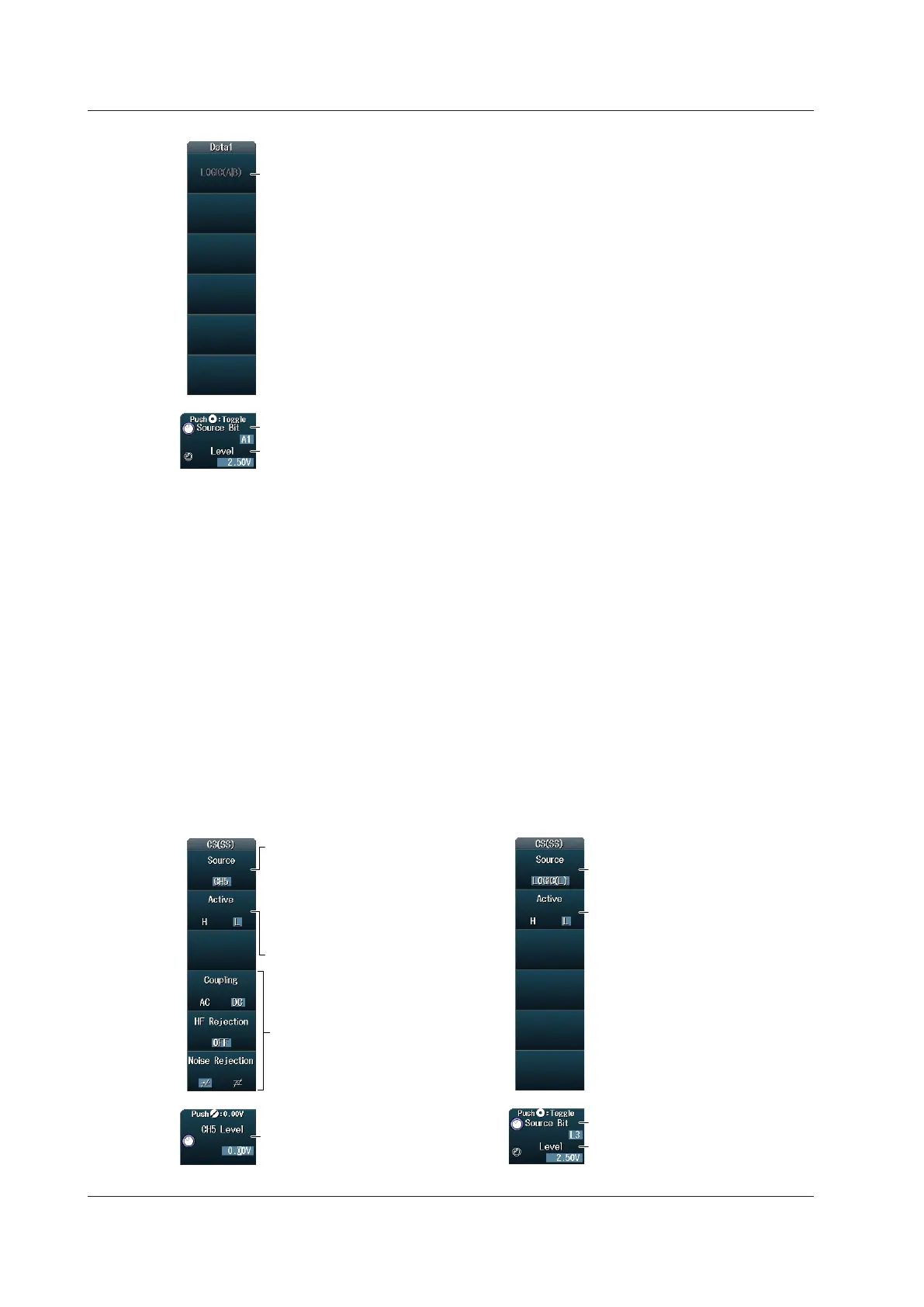
The data1 source is fixed to LOGIC(A|B).
* LOGIC(A|B) is available on models with the /L16 option.
When the Clock Source Is LOGIC(A|B)
Set the source bit (A0 to A7, B0 to B7).
Set the level used to detect data1 source states.
Setting the Data2 Source (Data2)
Press the Data2 soft key to display the one of the same menus that appears when you set the Data1
source. The menu that is displayed varies depending on the specified data source.
When the wiring system is 4 Wire, you can set the Data2 source as indicated below.
• When the clock source is a channel from CH1 to CH4: Set the source to CH1 to CH4.
• When the clock source is a channel from CH5 to CH8 or LOGIC(L): Set the source to CH5 to CH8
or LOGIC(L).
• When the clock source is LOGIC(A|B): Fixed to LOGIC(A|B).
* You can select CH8 or LOGIC(L), depending on which channel’s corresponding key (CH8 or L) is
illuminated. LOGIC(A|B) is available on models with the /L16 option.
Setting the Chip Select Source (CS(SS))
Press the CS(SS) soft key to display one of the menus shown below. The menu that is displayed
varies depending on the specified data source.
When the Chip Select Source Is a
Channel from CH1 to CH8
When the Chip Select Source
Is LOGIC(L)
Set the chip select source.
• When the clock source is a channel
from CH1 to CH4, set the source to
CH1 to CH4.
• When the clock source is a channel
from CH5 to CH8 or LOGIC(L), set
the source to CH5 to CH8.
Set the chip select source (LOGIC(L)).
Selectable only when the clock source
is set to CH5 to CH7 or LOGIC(L).
Set the active state (H, L).
Set the active state (H, L).
Set the level used to detect chip
select source states.
Set the source bit (L0 to L7).
Set the level used to detect chip
select source states.
Set the trigger coupling, HF rejection,
and noise rejection.
► section 2.3
* You can select CH8 or LOGIC(L), depending on which channel’s corresponding key (CH8 or L) is illuminated.
2.17 Triggering on SPI Bus Signals (Option)
 Loading...


