2-57
IM DLM4038-02EN
When the Clock Source Is LOGIC(A|B)
The chip select source is fixed to LOGIC(A|B).
Set the active state (H, L).
Set the source bit (A0 to A7, B0 to B7).
Set the level used to detect chip select source states.
* LOGIC(A|B) is available on models with the /L16 option.
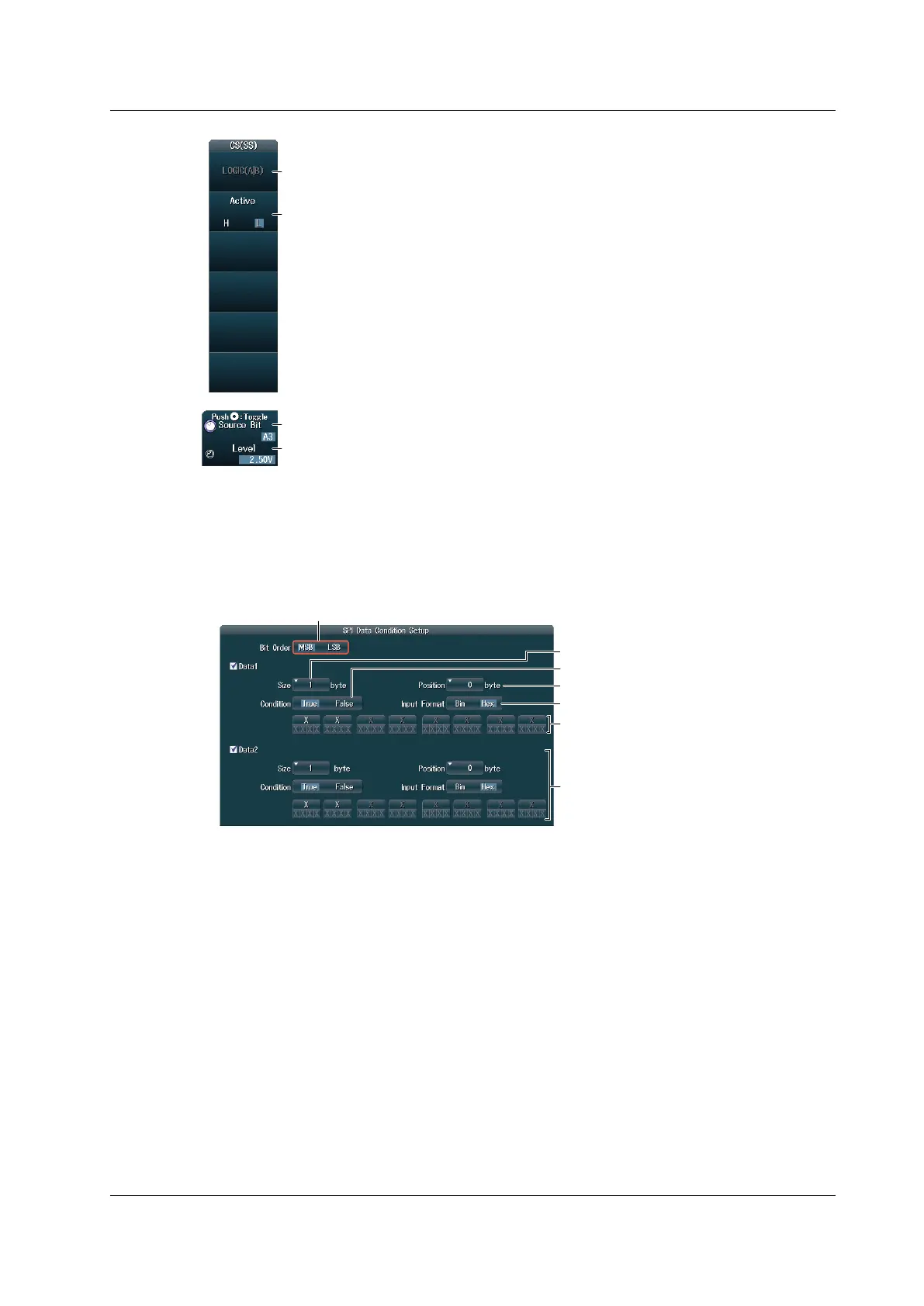
Setting Trigger Conditions (Condition Setup)
Press the Condition Setup soft key to display the following screen.
When Wiring System Is 4 Wire
Set the trigger conditions for Data1 and Data2.
• Set the data pattern.
• Set the comparison condition.
• Set the comparison start position.
• Set the data length.
• Set the data pattern input format.
Data2
Configure Data2 in the same manner that
you configure Data1.
This section only appears when mode is set
to 4 wire.
Data1
When Wiring System Is 3 Wire
Only set the trigger condition for Data1.
2.17 Triggering on SPI Bus Signals (Option)
 Loading...


