2-4
IM DL950-02EN
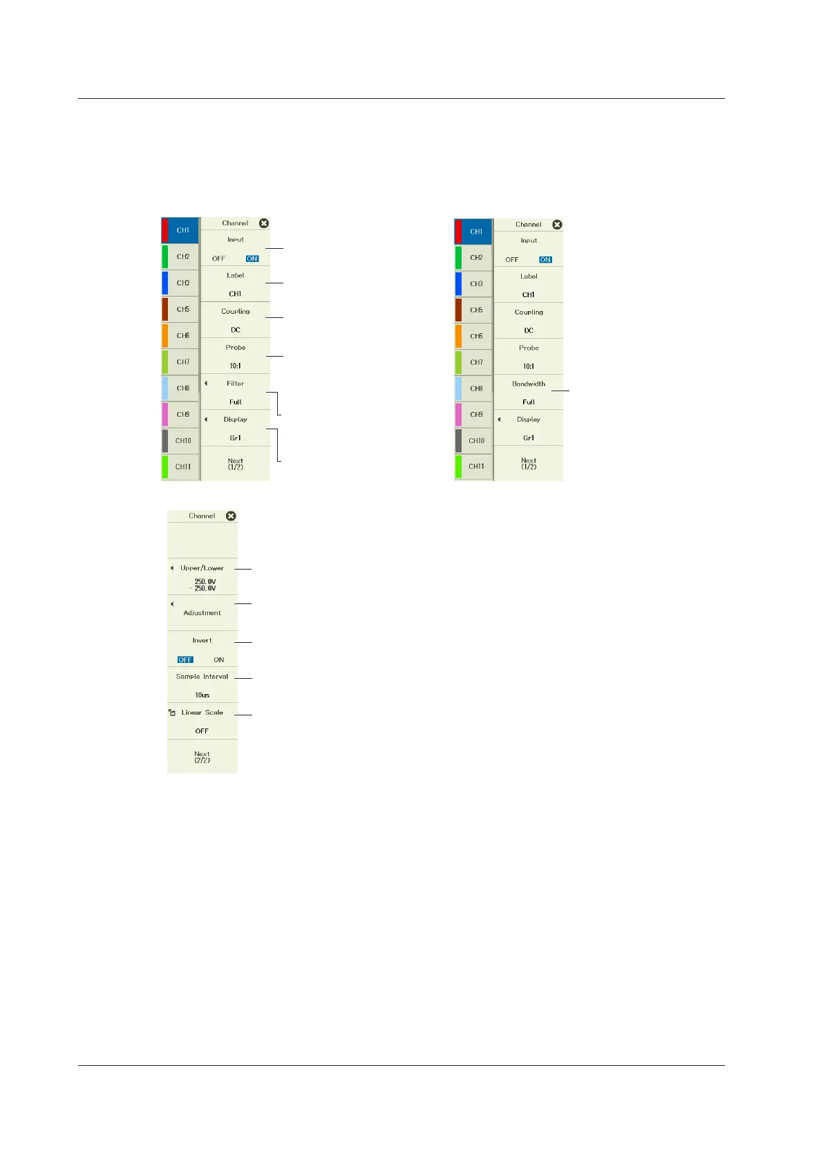
Recorder Mode
Turns the waveform
input on or off
Set the display label.
Channel setup menu (2/2)
See “Setting the Input
Coupling.”
See “Setting the Probe
Attenuation or the
Current-to-Voltage
Conversion Ratio.”
See “Setting the
Bandwidth Limit and
Digital Filter.”
See “Configuring the
Display.”
See “Setting the Display Range
in Recorder Mode.”
See “Setting the Adjustment (DC offset
cancellation, gain adjustment).”
Turns the inverted display on or off
See “Setting the Linear Scaling.”
Set the bandwidth limits.
See “Setting the Sample Interval.”
Channel Setup Menu on models other
than /G03 and /G05 models (1/2)
(Including the 720254 and 720256 on
/G03 and /G05 models)
Channel Setup Menu on /G03 and
/G05 models (1/2)
(excluding the 720254 and 720256)
2.1 Configuring Voltage Measurements (on modules other than 16-CH temperature/voltage input modules)

 Loading...


