2-5
IM DL950-02EN
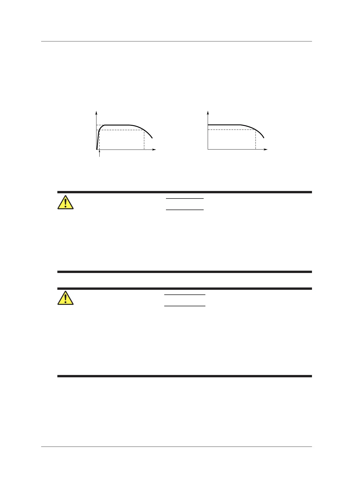
Setting the Input Coupling
The following figure shows the frequency characteristics when the input coupling is set to AC
or DC.
Please note that when set to AC, the instrument does not acquire low frequency signals or low
frequency components, as seen in the following figure.
0 dB
–3 dB
Attenuation
0 dB
–3 dB
–3 dB point*
–3 dB point when AC coupled
Input frequency
Input frequency
If AC is selected If DC is selected
* This value differs depending on the input module.
For details, section 7.15, “Module Specifications,” in the Getting
Started Guide (IM DL950-03EN).
CAUTION
If the input coupling is AC, in accordance with the frequency response, the input signal is
attenuated more in lower frequencies. As a result, even when a high voltage signal is actually
applied, it may not be measured as a high voltage signal. Furthermore, the over-range
indicator may not be displayed on the instrument screen. As necessary, switch the input
coupling to DC to check the input signal voltage.
Applying an input signal whose voltage exceeds the maximum input voltage of the input
module may damage the input section.
French
ATTENTION
Si le courant du couplage d’entrée est alternatif (CA), conforme à la réponse en fréquence, le
signal d’entrée est davantage atténué aux fréquences plus basses. Par conséquent, même si
vous appliqué un signal de tension élevée, ce dernier risque de ne pas être mesuré comme
tel. De plus, le voyant de dépassement de plage risque de ne pas s’afficher à l’écran. Le cas
échéant, basculez le couplage d’entrée sur CC (courant continu) afin de vérifier la tension du
signal d’entrée.
Si la tension du signal d’entrée dépasse la tension d’entrée maximale du module d’entrée, la
section d’entrée risque d’être endommagée.
2.1 Configuring Voltage Measurements (on modules other than 16-CH temperature/voltage input modules)

 Loading...


