22-4
IM DL950-02EN
Connecting Optical Fiber Cords
CAUTION
• Insert the optical fiber cord connectors slowly and straight into the optical ports. If you
shake the connector to the left and right or force it into the port, the optical connector or
optical port may be damaged.
• If you use optical connectors that do not meet the specifications, the instrument’s optical
ports may be damaged. Use optical connectors that are approved or used by national or
local telecom carriers and providers in your area.
French
ATTENTION
• Insérer lentement et droit le connecteur du cordon de fibre optique dans l’orifice optique en
tenant le connecteur. Si vous secouez le connecteur vers la gauche et la droite ou si vous
le forcez dans l’orifice, le connecteur ou l’orifice optique pourrait être endommagé.
• Toujours utiliser des connecteurs optiques conformes aux spécifications, à défaut de
quoi les ports optiques de l’DL950 pourraient être endommagés. Utiliser des connecteurs
optiques homologués ou utilisés par les entreprises et les fournisseurs de services de
télécommunications de votre région.
Connect multiple DL950s using the 720942 optical fiber cord, sold separately.
If you are preparing your own optical fiber cords, use multi-mode optical fiber cords (LC type).
1.
Properly align the optical fiber cord’s connector with the SFP module’s optical port, and insert
the connector.
Note
Clean the connector end face of the optical fiber cord before connecting it to the instrument. If dust is
adhered to the connector end face, it may damage the instrument's optical port. If this happens, the
instrument will not be able to communicate.
When cleaning the end face of the connector, use a cleaner dedicated to fiber optic cords.
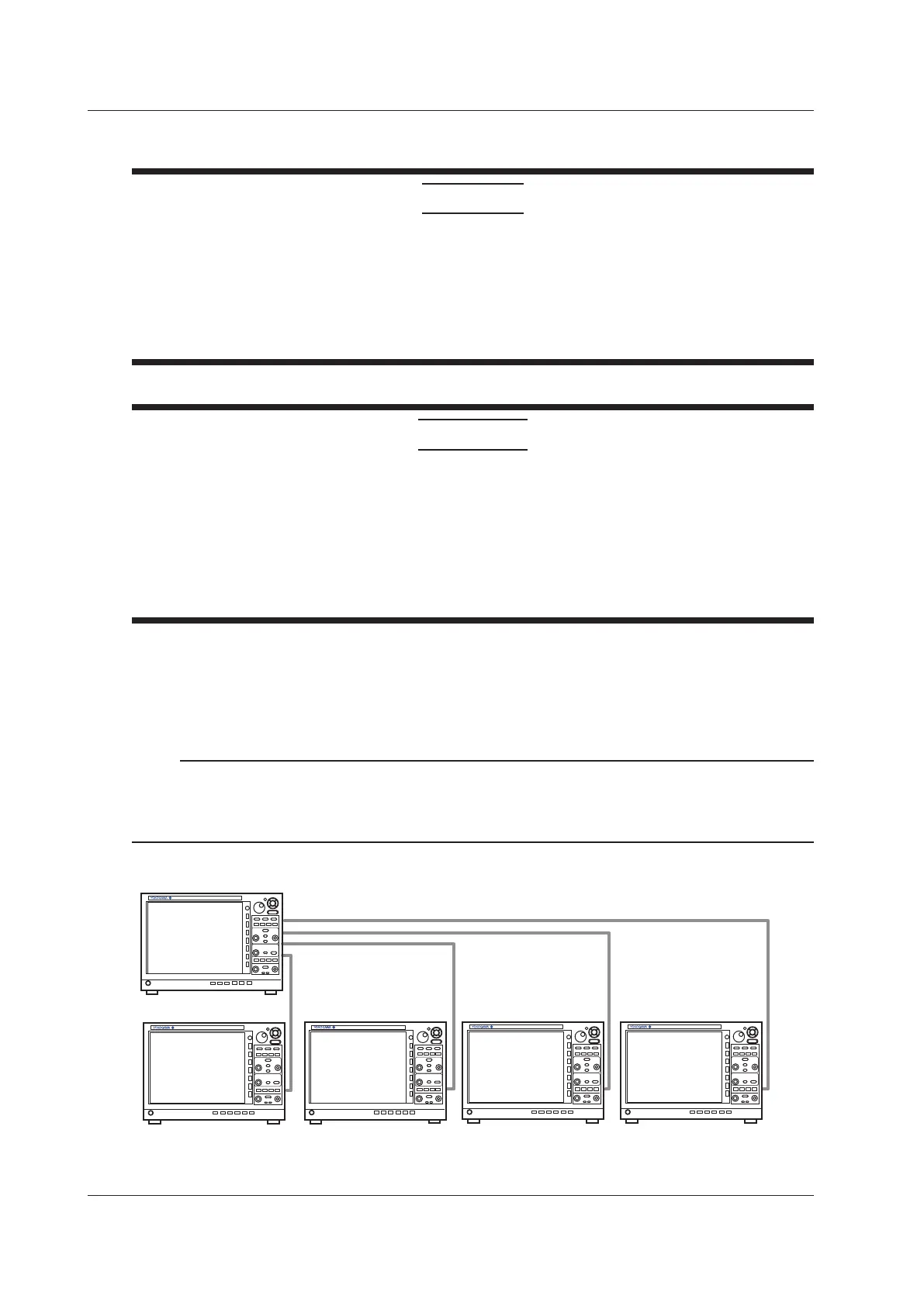
Connect the main unit and sub units in a star configuration as shown in the following figure.
Main unit
Sub unit 4
Sub unit 3
Sub unit 2
Sub unit 1
4
3
2
1
The sub unit numbers 1 to 4 are assigned in order from the top connector of the main unit to be
connected.
22.1 Connecting Multiple Instruments

 Loading...


