EasyManuals Logo
Home>Agilent Technologies>Laboratory Equipment>Nano Indenter G200

Agilent Technologies Nano Indenter G200 User Manual

Agilent Technologies Nano Indenter G200
478 pages
To Next Page IconTo Next Page
To Previous Page IconTo Previous Page
Page #448 background imageLoading...
Page #448 background image
Lateral Force Measurement F
Agilent Nano Indenter G200 User’s Guide F-4
Theory
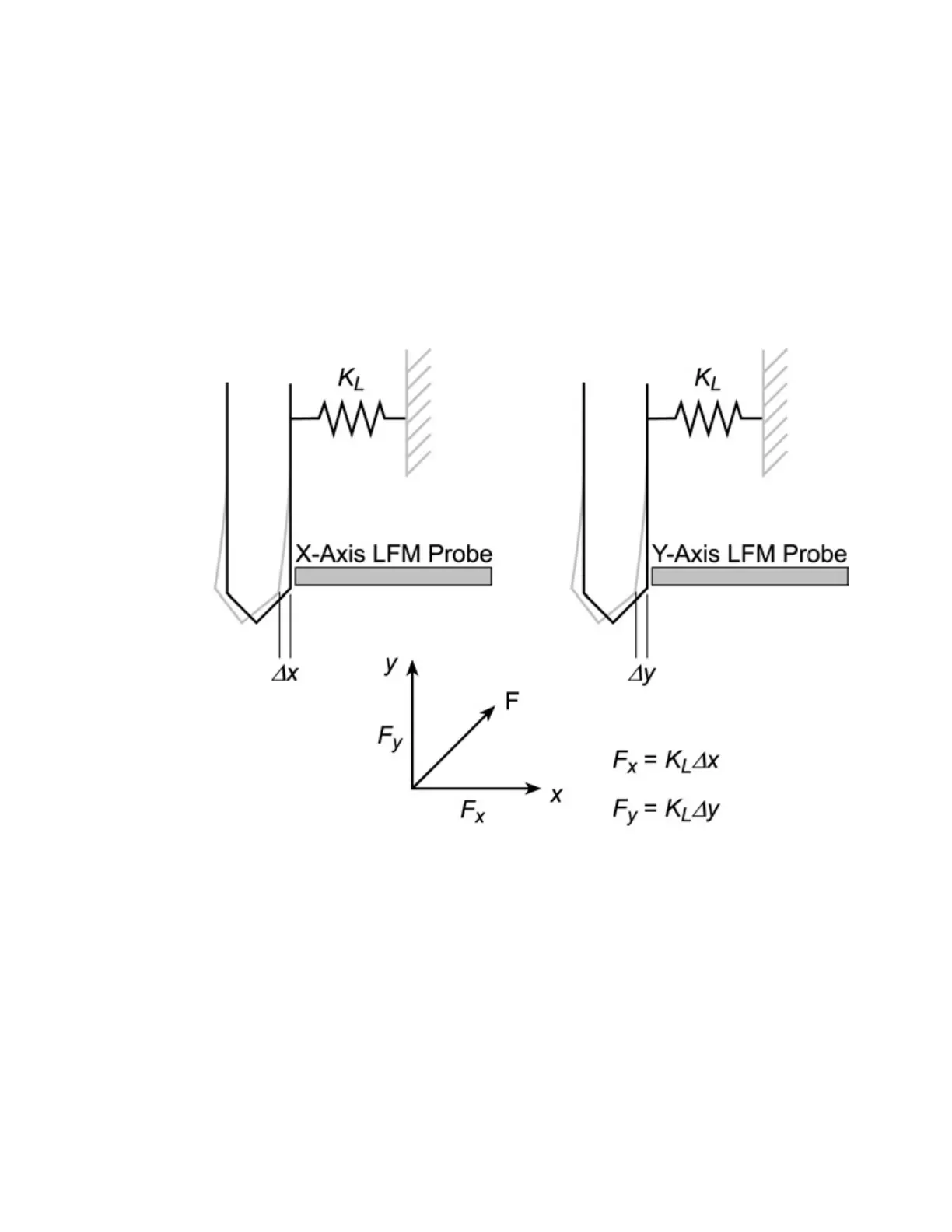
The LFM probes (shown in Figure 3- 12 on page 3-10) measure
deflection of the indenter shaft relative to its normal position. As shown
in
Figure F-3, K
L
represents the stiffness of the spring that supports the
shaft. The forces exerted in the directions of each of the probes are
calculated according to the formulas in the schematic.
Figure F-3Schematic for LFM illustrating indenter deflection measured
by LFM probes
The X and Y deflection values are stored in the _XDeflection and
_YDeflection channels. The resolved forces are stored in the _XForce
and _YForce channels.

Table of Contents

Questions and Answers:

Question and Answer IconNeed help?

Do you have a question about the Agilent Technologies Nano Indenter G200 and is the answer not in the manual?

Agilent Technologies Nano Indenter G200 Specifications

General IconGeneral
BrandAgilent Technologies
ModelNano Indenter G200
CategoryLaboratory Equipment
LanguageEnglish

Related product manuals