Chapter 4 INTERFACE SETTINGS
115
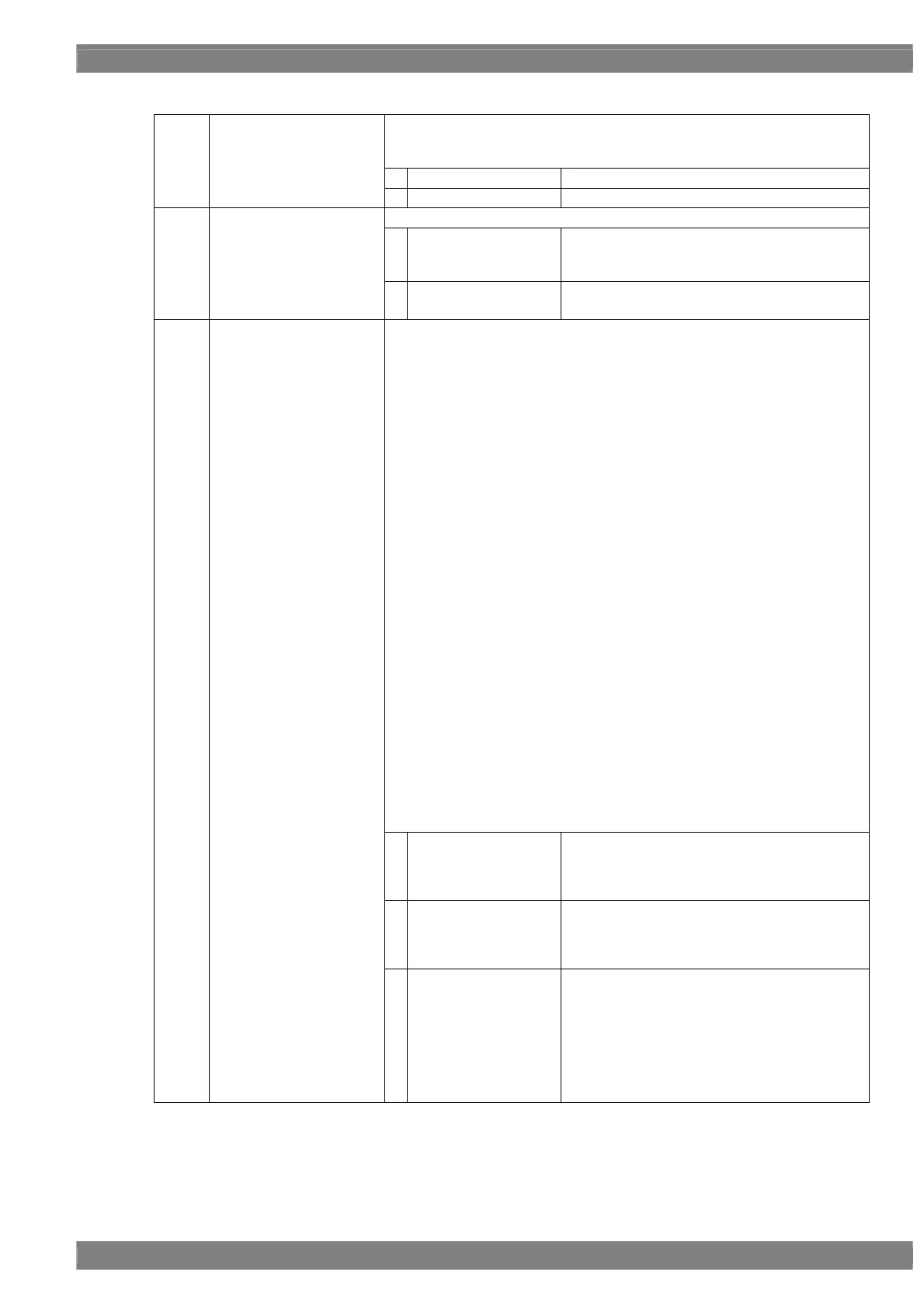
<iTMDS (4K×2K) unit setting parameters>
This sets On or Off for each channel.
The same settings as the ones described in “4.1.1 Setting the output
interfaces to ON or OFF” can also be established.
0
Off
No output.
(1)
Output 1ch (0/1)
Output 2ch (0/1)
Output Quad 1,2ch (0/1)
Output Quad 3,4ch (0/1)
1
On
Output.
This sets the output signal format.
0
DVI
The signals are output as DVI compatible
signals.
Eight bits per link are output.
(2)
iTMDS or DVI (0/1)
1
iTMDS
The signals are output as iTMDS signals.
Twelve bits per link are output.
This sets the bit length and link format of the images to be output from
iTMDS. A setting which is independent of the bit length for pattern drawing
can be selected. It is also possible to select the bit length automatically. The
portion by which the bit length for pattern drawing exceeds the bit length
which has been set here is discarded. A deficient portion is filled with zeros.
When the dot clock frequency is in the range of 25 MHz to 165 MHz,
Single Link can be selected, and the data can be distributed to and output
from output channels 1 and 2. With the VM-1824-A, the data can be
distributed to and output from channels 1, 2, 3 and 4.
When the dot clock frequency is in the range of 50 MHz to 330 MHz, Dual
Link can be selected, and the data can be distributed to and output from
output channels 1 and 2. With the VM-1824-A, the data of channels 1 and
2 and the data of channels 3 and 4 are combined and output by Dual Link.
When the dot clock frequency is in the range of 296 MHz to 660 MHz,
Quad Link can be selected, and the data can be output using output
channels 1 and 2. With the VM-1824-A, the data of channels 1, 2, 3 and 4
is combined and output by Quad Link.
When the dot clock frequency is in the range of 592 MHz to 1320 MHz, by
selecting Octal Link and by using two output boards, the data can be
output by combining the data of board #1 output channels 1 and 2 and the
data of board #2 output channels 1 and 2. With the VM-1824-A, the data
of board #1 channels 1, 2, 3 and 4 and data of board #2 channels 1, 2, 3
and 4 are combined and output by Octal Link.
* In the Quad Link or Octal Link mode, the 4K×2K screen splitting
operation which uses the frame memory on the board or boards is
performed.
* With the VM-1824-A, the Dual Link outputs of the VM-1824 are replaced
with Single Link outputs. Channel 1 of Dual Link corresponds to channels
1 and 2 of Single Link. Similarly, channel 2 of Dual Link corresponds to
channels 3 and 4 of Single Link.
“4.1.5 Setting the bit length (gray scale) for pattern drawing”
0
Single (8bit)
The data is output by Single Link from output
channels 1 and 2. The portion by which the bit
length for pattern drawing exceeds 8 bits is
discarded. (Max. 12 bits with the iTMDS format)
1
Dual (8bit)
The data is output by Dual Link from output
channels 1 and 2. The portion by which the bit
length for pattern drawing exceeds 8 bits is
discarded. (Max. 12 bits with the iTMDS format)
(3)
Mode (0/6)
2
Quad (8bit)
The data is output by Quad Link using output
channels 1 and 2. The portion by which the bit
length for pattern drawing exceeds 8 bits is
discarded. (Max. 12 bits with the iTMDS format)
The 4K×2K screen splitting operation which
uses the frame memory on the board is
performed. For details on the screen splitting
method, refer to “Split” in the next section.
 Loading...