124
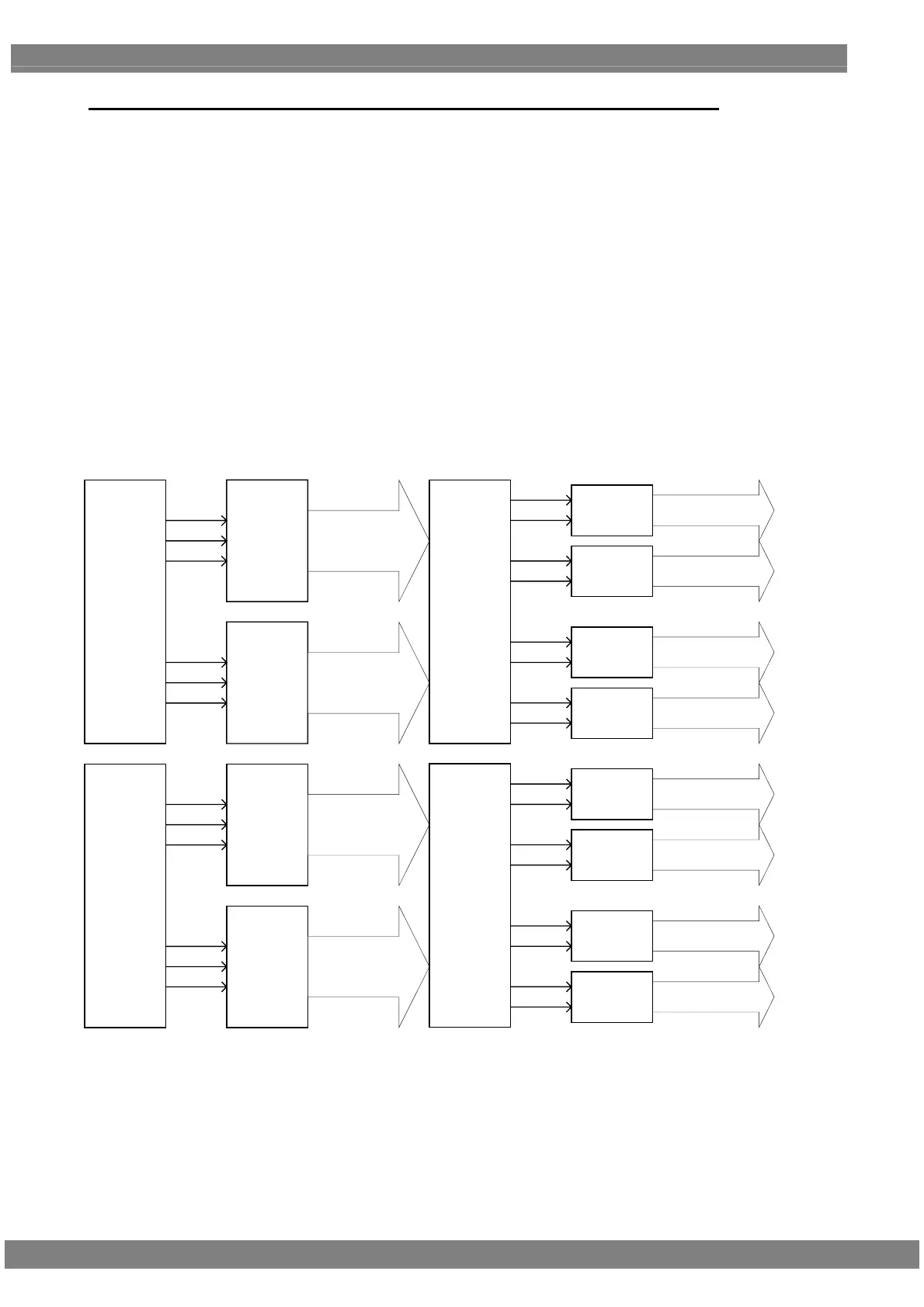
Specifications for modes during ×4 mode (Full HD 240 Hz mode) output
The ×4 mode is an output mode designed for the inspection of the FPD which support the Full HD 240 Hz output. By
connecting the output of the VG generator to the IA-1540 (iTMDS-LVDS converter box), the signal becomes 1/2 and
output in 8 channels.
The below explanation concerns the signals of 4 channels output from the VG generator. For an explanation about
an 8-channel output from LVDS, refer to section “4.13.3 Data transfer systems (V-By-One HS).”
4.13.3
* As shown in the figure below, the data of channels 1 to 4 for the Master and Slave of Dual Link of VM-1824 is
described in this section.
* Also described below in this section is the Single Link data of the VM-1824-A which is output as the data of
channels 1 to 4.
RGB 8-10Bit
[9:0]
Link0
Link1
Link2
Link3
Link4
Link5
1CH
2CH
2CH
Connector
3CH
4CH
【VG iTMDS 4CH 出力】
Dual
Link
Master
Dual
Link
Master
Dual
Link
Srave
Dual
Link
Srave
Link0
Link1
Link2
Link3
Link4
Link5
1CH
Connector
RGB 8-10Bit
[9:0]
RGB 8-10Bit
[9:0]
RGB 8-10Bit
[9:0]
IA-1540
LVDS
Converter
RGB 8-10Bit
[9:0]
RGB 8-10Bit
[9:0]
RGB 8-10Bit
[9:0]
RGB 8-10Bit
[9:0]
IA-1540
LVDS
Converter
RGB 8-10Bit
[9:0]
RGB 8-10Bit
[9:0]
RGB 8-10Bit
[9:0]
RGB 8-10Bit
[9:0]
1CH
LVDS OUT
2CH
LVDS OUT
3CH
LVDS OUT
4CH
LVDS OUT
5CH
LVDS OUT
6CH
LVDS OUT
7CH
LVDS OUT
8CH
LVDS OUT
TA~TE
TA~TE
TA~TE
TA~TE
TA~TE
TA~TE
TA~TE
TA~TE
【IA LVDS 8CH 出力】
【FullHD 240Hz 出力】
[VG generator iTMDS 4-channel output]
[IA converter box 8-channel output]
[Full HD 240 Hz output]
 Loading...