Chapter 4 INTERFACE SETTINGS
143
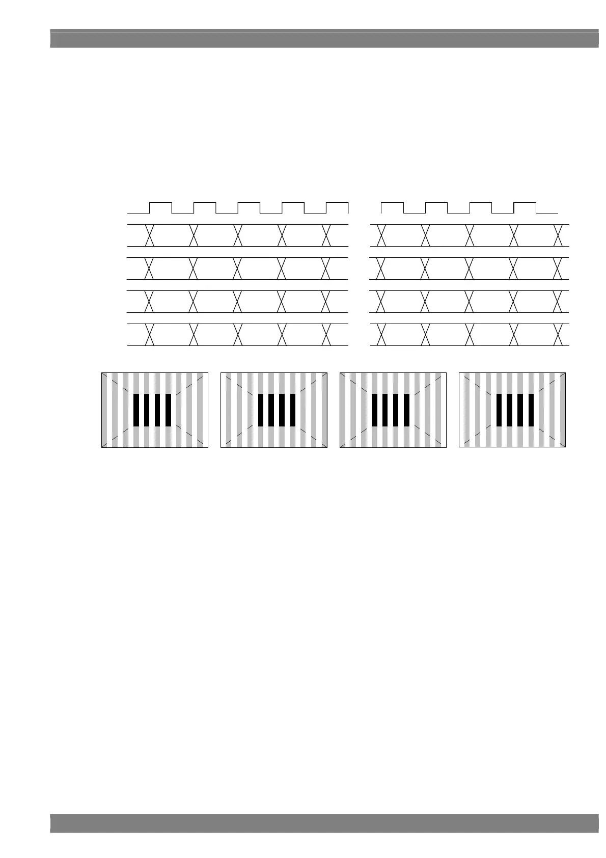
[2] 16Bit (Dual Link)
Dual Link images are output using channel 1 of the Master paired up with channel 1 of the Slave.
The higher 8 bits are output to channel 1.
Also, the Dual Link images are output using the 2-channel of the Master paired up with the 2-channel of the Slave.
The lower 8 bits are output to channel 2.
Given here as an example for explanatory purposes is a case where the resolution is 1280 × 1024, the dot clock
frequency is 108 MHz with the 16 bits output.
D 0 D 2 D 4 D 6
・・・
・・・
D 1272 D 1274 D 1276 D 1278
CLK
54MHz
1CH
2CH
3CH
4CH
D 1 D 3 D 5 D 7
・・・
D 1273 D 1275 D 1277 D 1279
・・・
D 1272 D 1274 D 1276 D 1278D 0 D 2 D 4 D 6
D 1273 D 1275 D 1277 D 1279
・・・
D 1 D 3 D 5 D 7
[7:0] [7:0] [7:0] [7:0] [7:0] [7:0] [7:0] [7:0]
[15:8] [15:8] [15:8] [15:8] [15:8] [15:8] [15:8] [15:8]
[15:8] [15:8] [15:8] [15:8] [15:8] [15:8] [15:8] [15:8]
[7:0] [7:0] [7:0] [7:0] [7:0] [7:0] [7:0] [7:0]
Upper Bit [15:8]
Upper Bit [15:8]
Lower Bit [7:0]
Lower Bit [7:0]
1CH 2CH 3CH 4CH
 Loading...