Chapter 4 INTERFACE SETTINGS
147
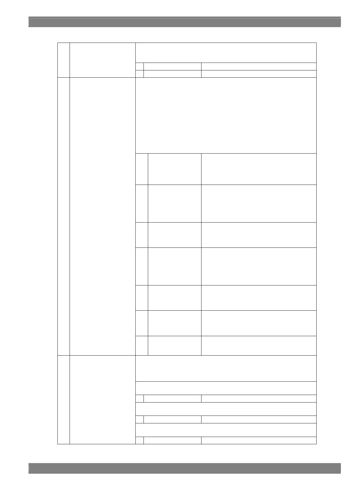
<LVDS setting parameters selected for each set of program data>
This sets On or Off for each channel.
The same settings as the ones described in “4.1.1 Setting the output
interfaces to ON or OFF” can also be established.
0
Off
No output.
(1)
Output 1,2ch (0/1)
Output 3,4ch (0/1)
1
On
Output.
This sets the bit length and link format of the images to be output from LVDS.
A setting which is independent of the bit length for pattern drawing can be
selected. It is also possible to select the bit length automatically. The portion
by which the bit length for pattern drawing exceeds the bit length which has
been set here is discarded. A deficient portion is filled with zeros.
“Quad” can be selected when the dot clock frequency ranges from 80 MHz
to 340 MHz, and data can be output.
“Dual” can be selected when the dot clock frequency ranges from 40 MHz to
270 MHz, and data can be output.
“Single” can be selected when the dot clock frequency ranges from 20 MHz
to 135 MHz, and data can be output.
“4.1.5 Setting the bit length (gray scale) for pattern drawing”
0
Single (10 bits)
The data is output by Single Link from output
channel 1. The portion by which the bit length for
pattern drawing exceeds 10 bits is discarded.
The same data as for output channel 1 is output
from output channels 2, 3 and 4.
1
Dual (10 bits)
The data is output by Dual Link from output
channels 1 and 2. The portion by which the bit
length for pattern drawing exceeds 10 bits is
discarded. The same data as for output
channels 1 and 2 is output from output channels
3 and 4.
2
Quad (10 bits)
The data is output by Quad Link from output
channels 1, 2, 3 and 4. The portion by which the
bit length for pattern drawing exceeds 10 bits is
discarded.
3
Single (16 bits)
The data is output by Single Link from output
channels 1 and 2. The portion by which the bit
length for pattern drawing is deficient from 16
bits length is filled with zeros. The same data as
for output channels 1 and 2 is output from output
channels 3 and 4.
4
Dual (16 bits)
The data is output by Quad Link from output
channels 1, 2, 3 and 4. The portion by which the
bit length for pattern drawing is deficient from 16
bits length is filled with zeros.
(3)
5
Single (Auto)
The data is output by Single Link. Single (10
bits) or Single (16 bits) is automatically
selected depending on the bit length for pattern
drawing.
(2)
Mode (0/1)
6
Dual (Auto)
The data is output by Dual Link. Dual (10 bits)
or Dual (16 bits) is automatically selected
depending on the bit length for pattern drawing.
This splits the images to be output, and sets channels 1, 2, 3 and 4 as the
output channels.
When a setting other than Normal is selected, all other outputs are shut
down.
The setting below can be selected only when the Single (10 bits) mode has
been set.
0
Normal
The setting below can be selected only when the Single (16 bits) mode has
been set.
0
Normal
The setting below can be selected only when the Single (Auto) mode has
been set.
(3)
Split
0
Normal
 Loading...