Chapter 4 INTERFACE SETTINGS
153
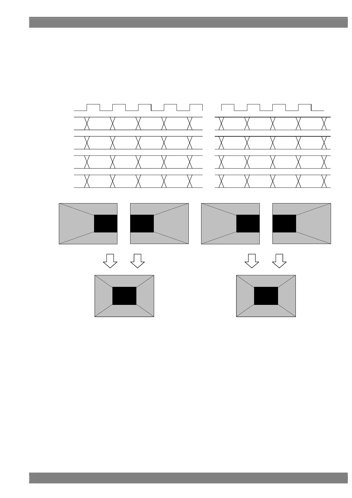
Setting (4) [Dual (10 bits)], [2 split]
The images are output with channels 1 and 2 forming one set and channels 3 and 4 forming another set. If this is
described with the channel 1 and 2 set used as an example, the left half of the image is allocated and output to
channel 1, and the right half of the image is allocated and output to channel 2.
The output level is 8 to 10 bits.
The example is that the resolution is 1280 × 1024, the dot clock frequency is 108 MHz, with the 10 bits output.
D 0
[9:0]
D 1 D 2 D 3
・・・
・・・
[9:0] [9:0] [9:0]
D 636
[9:0]
D 637 D 638 D 639
[9:0] [9:0] [9:0]
CLK
54MHz
D 640
[9:0]
D 641 D 642 D 643
・・・
[9:0] [9:0] [9:0]
D 1276
[9:0]
D 1277 D 1278 D 1279
[9:0] [9:0] [9:0]
1CH
2CH
3CH
4CH
D 0
[9:0]
D 1 D 2 D 3
・・・
[9:0] [9:0] [9:0]
D 636
[9:0]
D 637 D 638 D 639
[9:0] [9:0] [9:0]
D 640
[9:0]
D 641 D 642 D 643
・・・
[9:0] [9:0] [9:0]
D 1276
[9:0]
D 1277 D 1278 D 1279
[9:0] [9:0] [9:0]
1CH 2CH 3CH 4CH
 Loading...