154
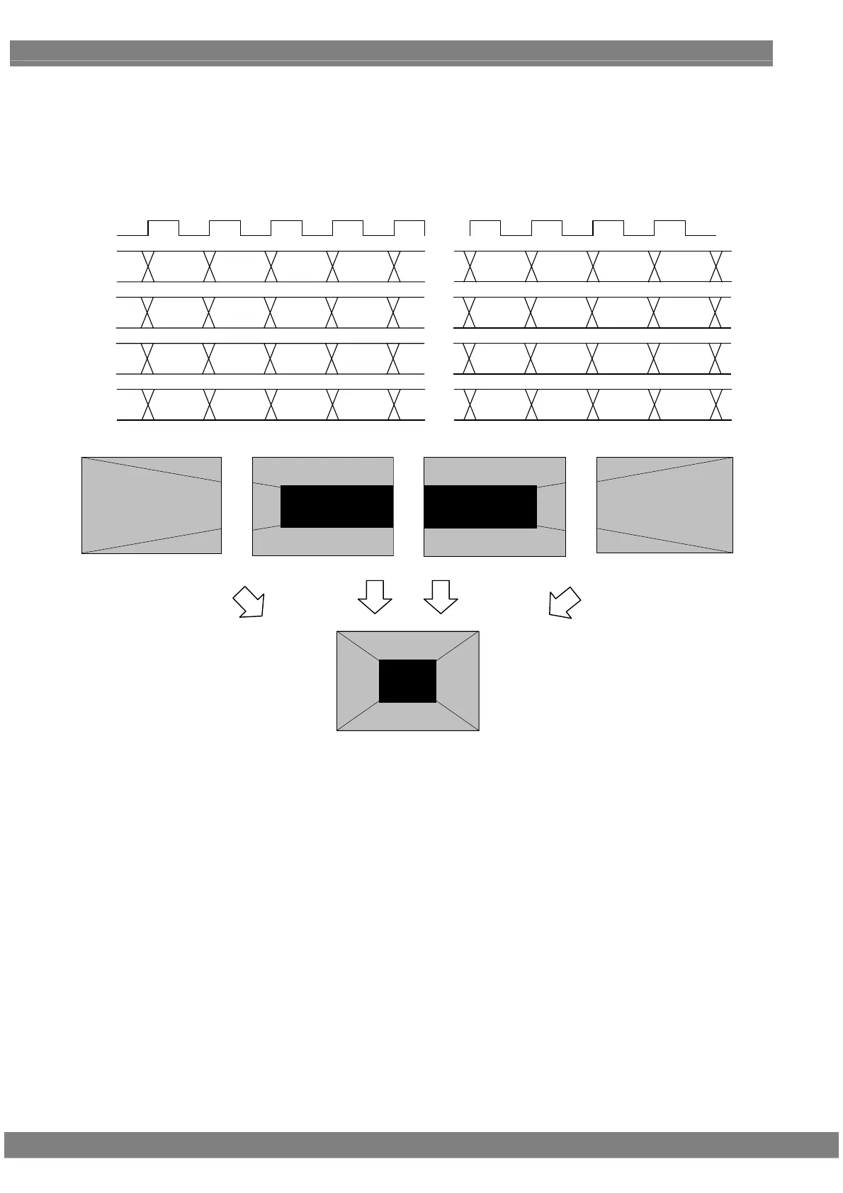
Setting (5) [Quad (10 bits)], [4 split]
The images are split into four parts horizontally, and allocated from the left to channels 1, 3, 2 and 4 in this order.
The output level is 8 to 10 bits.
The example is that the resolution is 1280 × 1024, the dot clock frequency is 108 MHz, with 10 bits output level.
D 0
[9:0]
D 1 D 2 D 3
・・・
・・・
[9:0] [9:0] [9:0] [9:0] [9:0] [9:0] [9:0]
CLK
27MHz
D 316 D 317 D 318 D 319
1CH
2CH
3CH
4CH
[9:0]
・・・
[9:0] [9:0] [9:0]
D 1276
[9:0]
D 1277 D 1278 D 1279
[9:0] [9:0] [9:0]
D 960 D 961 D 962 D 963
D 636 D 637 D 638 D 639
D 320
[9:0]
D 321 D 322 D 323
・・・
[9:0] [9:0] [9:0] [9:0] [9:0] [9:0] [9:0]
[9:0]
・・・
[9:0] [9:0] [9:0]
D 956
[9:0]
D 957 D 958 D 959
[9:0] [9:0] [9:0]
D 640 D 641 D 642 D 643
1CH 3CH 2CH 4CH
 Loading...