Chapter 4 INTERFACE SETTINGS
155
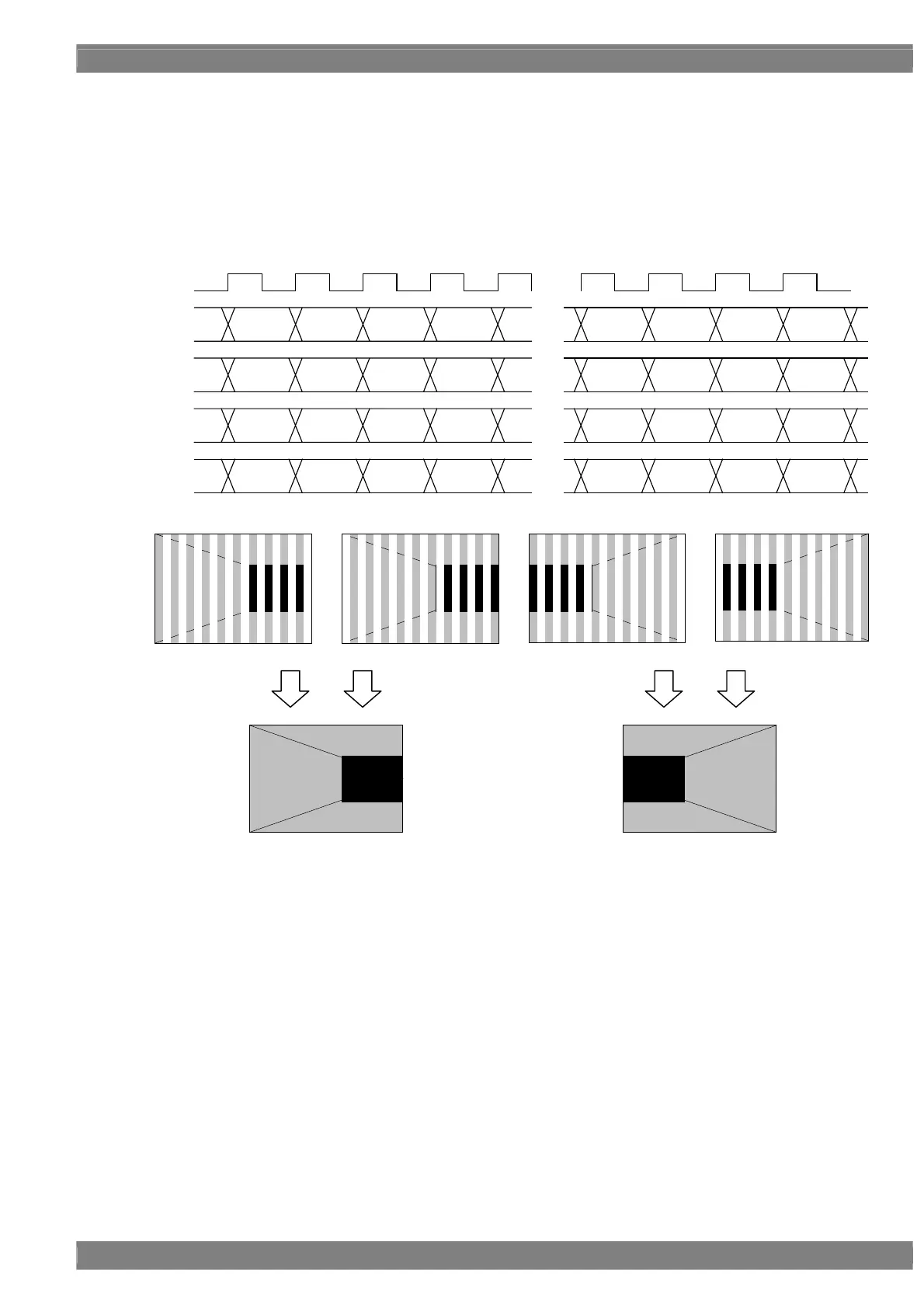
Setting (6) [Quad (10 bits)], [2 split]
The images are output with channels 1 and 3 forming one set and channels 2 and 4 forming another set. The left half
of the image is allocated and output to the channel 1 and 3 set, and the right half of the image is allocated to the
channel 2 and 4 set.
The output level is 8 to 10 bits.
The example is that the resolution is 1280 × 1024, the dot clock frequency is 108 MHz, with 10 bits output level.
D 0
[9:0]
D 2 D 4 D 6
・・・
・・・
[9:0] [9:0] [9:0] [9:0] [9:0] [9:0] [9:0]
CLK
27MHz
D 632 D 634 D 636 D 638
1CH
2CH
3CH
4CH
[9:0]
・・・
[9:0] [9:0] [9:0]
D 1273
[9:0]
D 1275 D 1277 D 1279
[9:0] [9:0] [9:0]
D 641 D 643 D 645 D 647
D 633 D 635 D 637 D 639
D 1
[9:0]
D 3 D 5 D 7
・・・
[9:0] [9:0] [9:0]
[9:0] [9:0] [9:0] [9:0]
[9:0]
・・・
[9:0] [9:0] [9:0]
D 1272
[9:0]
D 1274 D 1276 D 1278
[9:0] [9:0] [9:0]
D 640 D 642 D 644 D 646
1CH 2CH 3CH 4CH
 Loading...