Chapter 4 INTERFACE SETTINGS
159
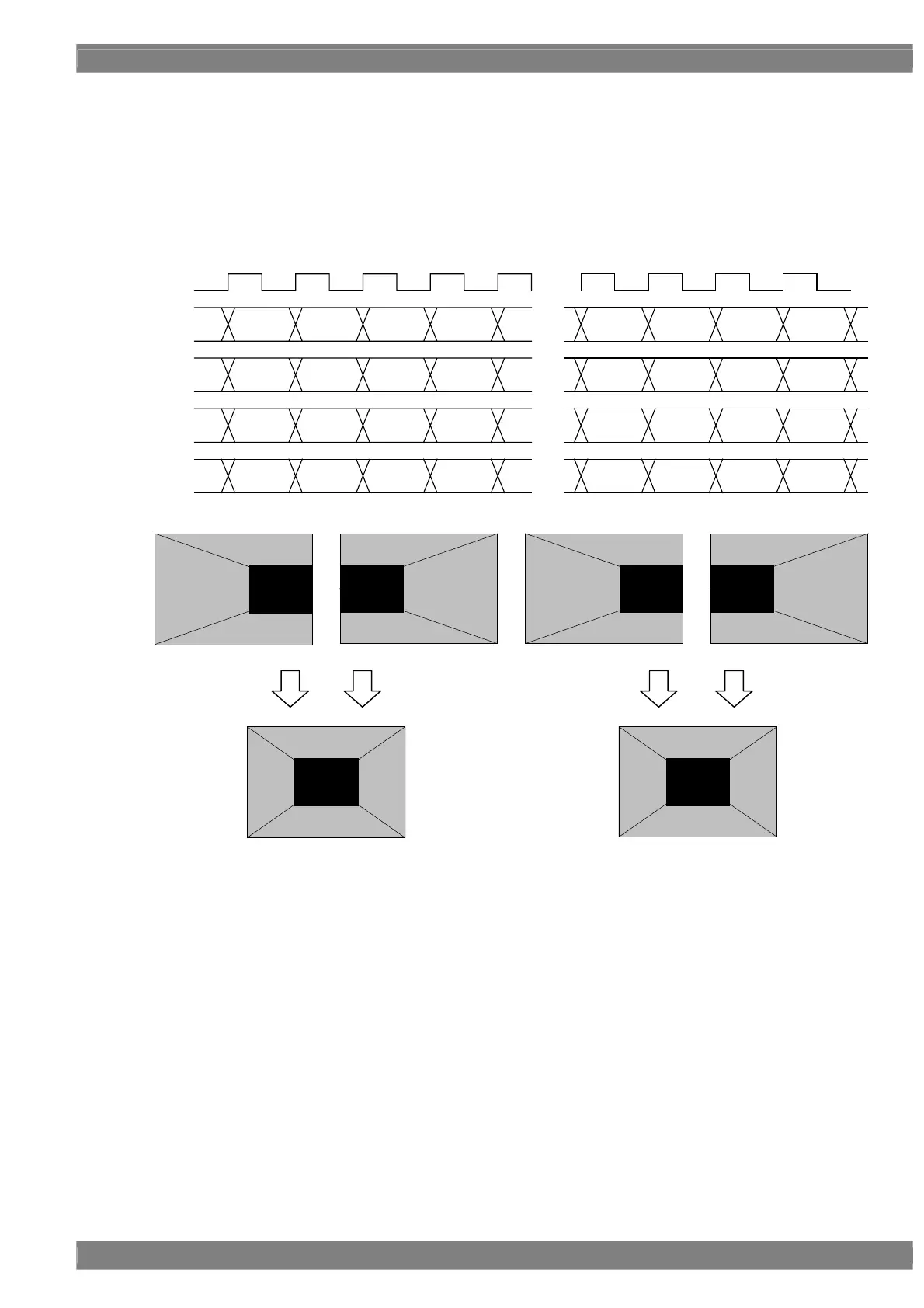
Setting (3) [Dual (16 bits)], [2 split], configuration [10 + 6 bits]
With channels 1 and 3 forming one set and channels 2 and 4 forming another set, the left half of the image is output
using one set and the right half of the image is output using the other set.
The 10 upper bits are output to channels 1 and 2, and the remaining 6 lower bits are output to channels 3 and 4.
The example is that the resolution is 1280 × 1024, the dot clock frequency is 108 MHz with 16 bits level, 10 bits are
output to channel 1 and 6 bits are output to channel 2.
D 0 D 1 D 2 D 3
・・・
・・・
D 636 D 637 D 638 D 639
CLK
54MHz
1CH
2CH
3CH
4CH
D 640 D 641 D 642 D 643
・・・
D 1276 D 1277 D 1278 D 1279
[15:6] [15:6] [15:6] [15:6]
[5:0] [5:0] [5:0] [5:0]
[15:6] [15:6] [15:6] [15:6]
[5:0] [5:0] [5:0] [5:0]
D 640 D 641 D 642 D 643
・・・
D 1276 D 1277 D 1278 D 1279
[15:6] [15:6] [15:6] [15:6] [15:6] [15:6] [15:6] [15:6]
D 0 D 1 D 2 D 3
・・・
D 636 D 637 D 638 D 639
[5:0] [5:0] [5:0] [5:0] [5:0] [5:0] [5:0] [5:0]
Upper Bit [15:6]
Upper Bit [15:6]
Lower Bit [5:0] Lower Bit [5:0]
Upper Bit [15:6]
Lower Bit [5:0]
1CH 2CH 3CH 4CH
 Loading...