168
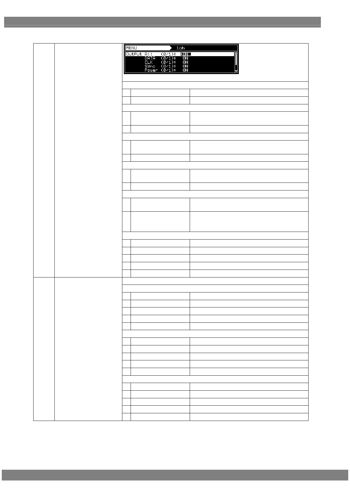
Parallel data setting parameters
Output All
0
OFF
1
ON
DATA
0
Hiz
This sets the parallel data to the high-impedance
(HiZ) state.
1
ON
This outputs the parallel data.
CLK
0
Hiz
This sets the CLK signal to the high-impedance
(HiZ) state.
1
ON
This outputs the parallel clock signal.
Sync
0
Hiz
This sets the parallel clock signal to the
high-impedance (HiZ) state.
1
ON
This outputs the parallel clock signal.
Power
0
Hiz
This sets the parallel power supply to the
high-impedance (HiZ) state.
1
ON
This outputs the parallel power.
For further details on the settings, refer to “1.5.6
Parallel unit”
SW
0
CS
CS output from SW
1
VD
VD output from SW
2
HD
HD output from SW
3
Low
Fix SW to Low
(1)
1ch
4
High
Fix SW to High
The settings from Output to Power are the same as for channel 1.
SW1
0
CS
CS output from SW1
1
VD
VD output from SW1
2
HD
HD output from SW1
3
Low
Fix SW1 to Low
4
High
Fix SW1 to High
SW2
0
HS
HS output from SW2
1
VD
VD output from SW2
2
HD
HD output from SW2
3
Low
Fix SW2 to Low
4
High
Fix SW2 to High
SW3
0
VS
VS output from SW3
1
VD
VD output from SW3
2
HD
HD output from SW3
3
Low
Fix SW3 to Low
(2)
2ch
4
High
Fix SW3 to High
 Loading...