Chapter 4 INTERFACE SETTINGS
169
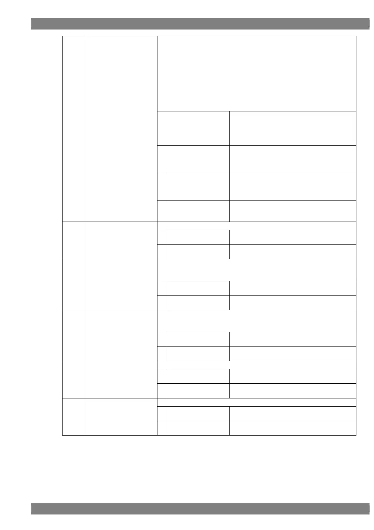
This sets the bit length and link format of the images to be output from the
parallel connector. A setting which is independent of the bit length for pattern
drawing can be selected. It is also possible to select the bit length
automatically. The portion by which the bit length for pattern drawing exceeds
the bit length which has been set here is discarded. A deficient portion is filled
with zeros.
“Single” can be selected when the dot clock frequency ranges from 0.1 MHz
to 100 MHz, and the data can be output.
“Dual” can be selected when the dot clock frequency ranges from 0.2 MHz to
200 MHz, and the data can be output.
“4.1.5 Setting the bit length (gray scale) for pattern drawing”
0
Single (8 bits)
The data is output by Single Link from output
channel 1. The portion by which the bit length for
pattern drawing exceeds 8 bits is discarded. The
same data as for output channel 1 is output for
channel 2.
1
Dual (8 bits)
The data is output by Dual Link from output
channels 1 and 2. The portion by which the bit
length for pattern drawing exceeds 8 bits is
discarded.
2
Single (16 bits)
The data is output by Single Link from output
channels 1 and 2. The portion by which the bit
length for pattern drawing is deficient from 16 bits
is discarded.
(3)
Mode (0/1)
3
Single (Auto)
The data is output by Single Link. Single (10
bits) or Single (16 bits) is automatically selected
depending on the bit length for pattern drawing.
This selects whether to reverse the polarity of the parallel clock signal.
0
Nega
This outputs the clock signal with a reversed
polarity.
(4)
Polarity CLK (0/1)
1
Posi
This outputs the clock signal with a non-reversed
polarity.
This selects whether to reverse the polarity of the parallel HD.
For further details of the setting procedure, refer to “3.2 Vertical timing data
editing.”
0
Nega
This outputs the clock signal with a reversed
polarity.
(5)
HD (0/1)
1
Posi
This outputs the clock signal with a non-reversed
polarity.
This selects whether to reverse the polarity of the parallel VD.
For further details of the setting procedure, refer to “3.2 Vertical timing data
editing.”
0
Nega
This outputs the clock signal with a reversed
polarity.
(6)
VD (0/1)
1
Posi
This outputs the clock signal with a non-reversed
polarity.
This selects whether to reverse the polarity of the parallel CS.
0
Nega
This outputs the clock signal with a reversed
polarity.
(7)
CS (0/1)
1
Posi
This outputs the clock signal with a non-reversed
polarity.
This selects whether to reverse the polarity of the parallel DISP.
0
Nega
This outputs the clock signal with a reversed
polarity.
(8)
DISP (0/1)
1
Posi
This outputs the clock signal with a non-reversed
polarity.
 Loading...