Chapter 4 INTERFACE SETTINGS
221
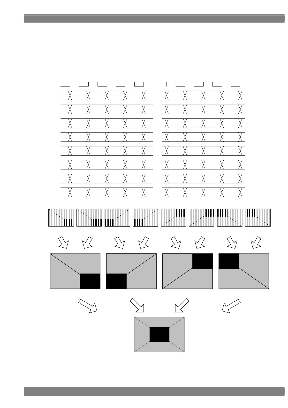
[1] MODE0 (8 Lane) - Normal
The image is split into 4 in the form of a square divided into 4 equal parts and assigned in sequence using lanes 1
and 2 for the top left part, lanes 3 and 4 for the top right part, lanes 5 and 6 for the bottom left part and lanes 7 and 8
for the bottom right part.
Given here as an example where the resolution is 4096 × 2048, the dot clock frequency is 592 MHz and the output
bit depth is 10 bits.
CLK
74MHz
Lane 1
Lane 2
Lane 3
Lane 4
・・・
L0~L1079
L0~L1079
L1080~L2159
L1080~L2159
D 2044
D 2045
D 2046
D 2047
[9:0] [9:0] [9:0] [9:0]
D 0
[9:0]
D 2
D 3
・・・
[9:0] [9:0] [9:0]
[9:0] [9:0] [9:0] [9:0][9:0]
・・・
[9:0] [9:0] [9:0]
[9:0] [9:0] [9:0] [9:0][9:0]
・・・
[9:0] [9:0] [9:0]
D 4092
[9:0]
D 4093
D 4094
D 4095
[9:0] [9:0] [9:0]
[9:0]
・・・
[9:0] [9:0] [9:0]
D 2048
D 2049
D 2050
D 2051
Lane 5
Lane 6
Lane 7
Lane 8
L0~L1079
L0~L1079
L1080~L2159
L1080~L2159
D 1
D4 D6
D7D5
D 2040
D 2041
D 2042
D 2043
D2052
D2053
D2054
D2055
D4088
D4089
D4090
D4091
D 2044
D 2045
D 2046
D 2047
[9:0] [9:0] [9:0] [9:0]
D 0
[9:0]
D 2
D 3
・・・
[9:0] [9:0] [9:0]
[9:0] [9:0] [9:0] [9:0][9:0]
・・・
[9:0] [9:0] [9:0]
[9:0] [9:0] [9:0] [9:0][9:0]
・・・
[9:0] [9:0] [9:0]
D 4092
[9:0]
D 4093
D 4094
D 4095
[9:0] [9:0] [9:0]
[9:0]
・・・
[9:0] [9:0] [9:0]
D 2048
D 2049
D 2050
D 2051
D 1
D4 D6
D7D5
D 2040
D 2041
D 2042
D 2043
D2052
D2053
D2054
D2055
D4088
D4089
D4090
D4091
Lane 1 Lane 2 Lane 3 Lane4 Lane 5 Lane 6 Lane 7 Lane 8
Lane 5-6 Lane 7-8Lane 1-2 Lane 3-4
 Loading...