Description of the Software Modules and Parameters
Parameter manual b maXX BM3000
Document no.: 5.12001.07
509
of 820
4
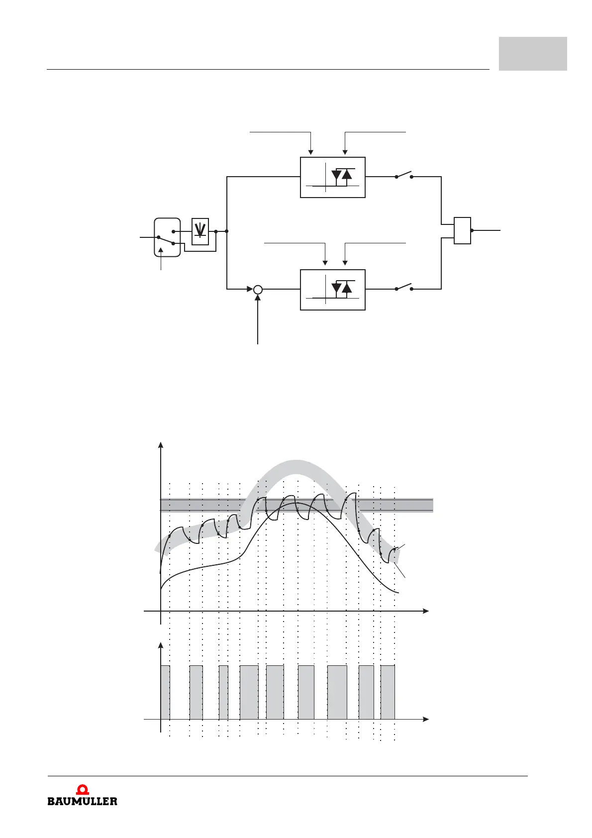
Figure 170: Combination absolute and relative thresholds
The output of the two-level controller is activated if the actual value remains under the rel-
ative and absolute lower threshold and is deactivated, if the actual value exceeds the rel-
ative or absolute upper threshold (NOR logic).
Figure 171: Combination absolute and relative thresholds
-
1
0
1
152.4
5000_0205_rev01_int.cdr
152.5
152.7 152.8
152.2
152.6
Status word 3,
bit 0
Mode bit 0
152.1
Lower
absolute threshold
Lower
relative threshold
Upper
absolute threshold
Upper
relative threshold
Mode bit 1
152.1
Relative comparison value
Absolute value
Source number
2-point-controller
input
Absolute threshold
Relative threshold
mode, bit 2
152.1
t
h(t)
y
t
rel. on
5000_0208_rev01_int.cdr
rel. lower threshold
abs. lower threshold
rel. upper threshold
abs. upper threshold
rel. compare value