INSTALLATION AND STARTUP
1MANUL220 Belanger, Inc.® * PO BOX 5470. * Northville, MI 48167-5470 * Ph (248) 349-7010 * Fax (248) 380-9681 4-51
Chapter 4 Frame and Carriage Assembly
Mounting the Exit Arm Accessories
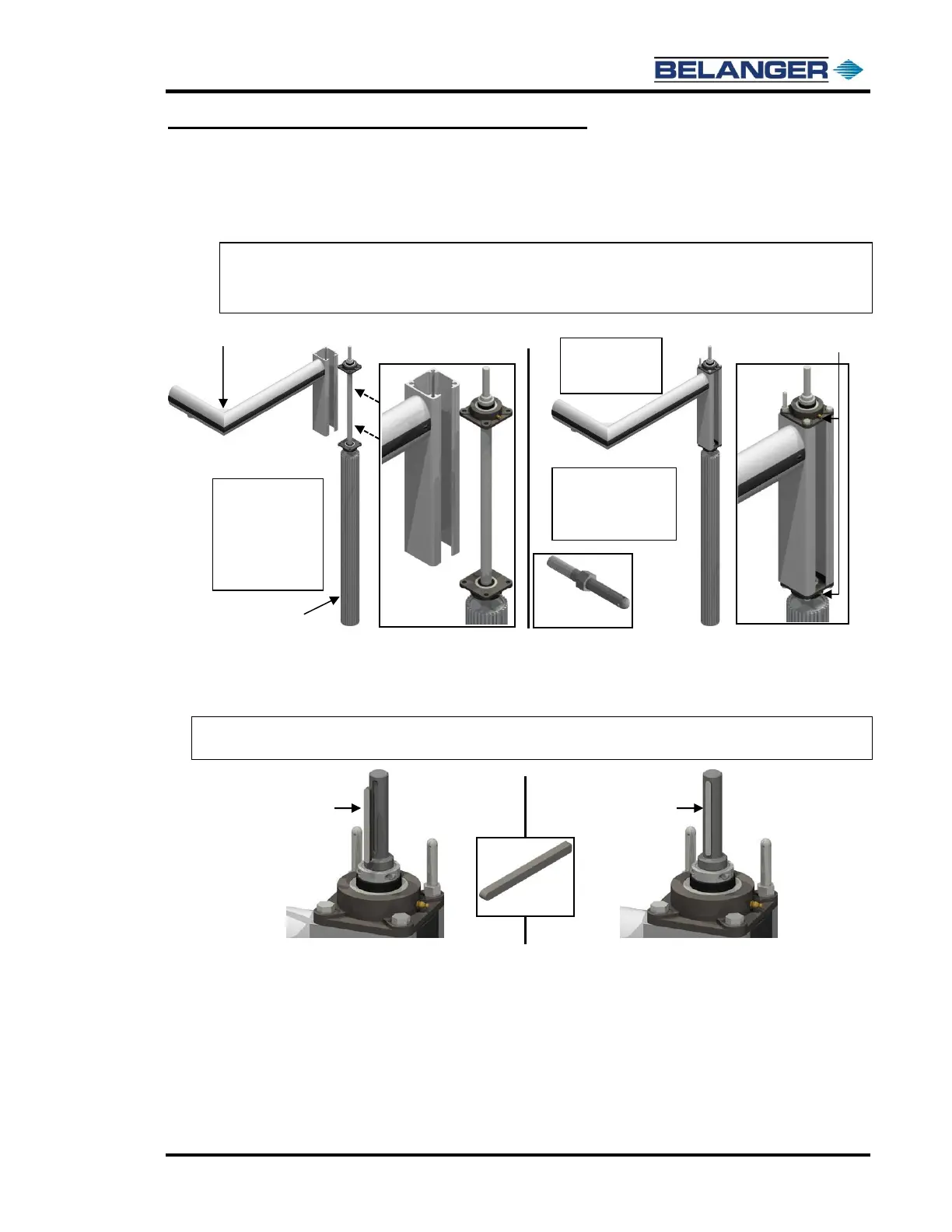
3) Locate one of the Exit Hub and Shaft Assemblies, lift it up and set it onto the bearing extrusion as
shown below.
Secure the bearing with two provided 9/16 x 1-1/12” bolts and two Torque Plate Studs.
Note: Verify that the Torque Plate Studs are in the location and orientation shown below (always facing
inward from the center of the bay).
Note: Verify that the grease fittings face outward for ease of maintenance.
4) Locate 1STEEL-KY150 and place it into the key slot. See the image below.
Slide the correct motor onto the shaft as shown later in this chapter in Mounting the Entrance
and Exit Motors and Gearboxes.
Note: NEVER FORCE THE GEABOX ON TO THE SHAFTS. SAND OR DEBUR THEM IF
NECESSARY. APPLY ANTI-SEIZE TO THE TOP OF THE SHAFT AND ON KEYSTOCK.
 Loading...


