INSTALLATION AND STARTUP
4-2 Belanger, Inc.® * PO BOX 5470. * Northville, MI 48167-5470 * Ph (248) 349-7010 * Fax (248) 380-9681 1MANUL220
Chapter 4 Frame and Carriage Assembly
Floor Mounted Frame
Note: Follow the torque specifications in Chapter 1 of this manual when tightening bolts.
Note: It is imperative to wash quality and cycle time that leveling techniques at the end of
this chapter are performed.
Note: See Chapter 17 for installation of Onboard Drying Applications.
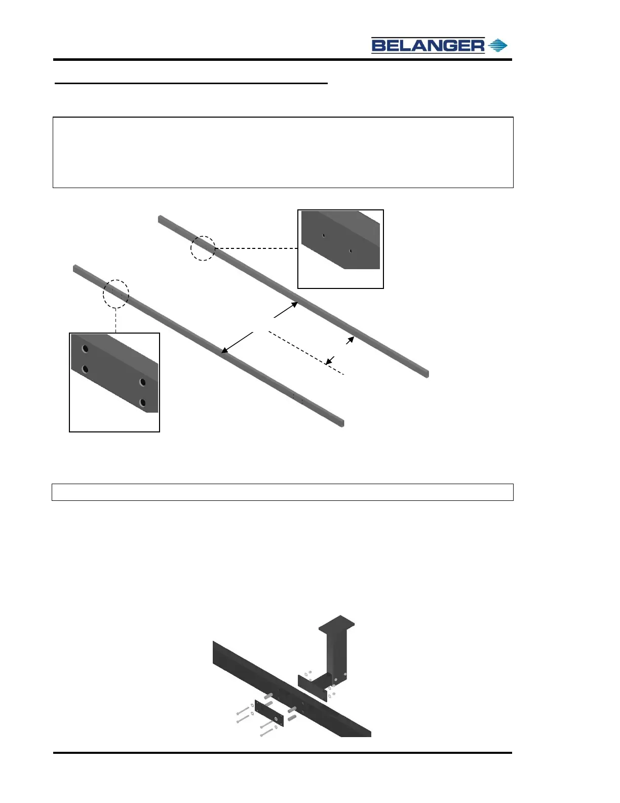
Frame Rail Parts Identification (Overhead View)
1) Verify all the bay length, width, and height considerations highlighted in Chapter 3. Determine the
position of the machine and the centerline of the doors.
2) Determine if any of the arms need to be de-stroked.
Note: The FreeStyler® uses a universal rail, so both rails are identical.
3) Place the two FreeStyler® rails in the bay considering the notes in the above diagram. If from the
height considerations, the carriage can be placed onto the rails with the rail spacing set to 92 1/4’’,
then set rail spacing to that distance at this time. If the rails need to be separated to 100’’ to lift the
carriage up in between the rails, set rail spacing to that distance at this time.
4) Take the four L-Bracket assemblies apart as shown below.
5) Take the sixteen compression rods and slide them into the larger diameter holes in the rails.
6) Attach the four L-Brackets to the frame using the 1/2-13 x 4-1/2‘’ bolts, 1/2‘’ flat washers, bolt on
detail plate, and 1/2’’ Nylock™ nuts, as shown in the diagram below.