INSTALLATION AND STARTUP
13-6 Belanger, Inc. ®* PO BOX 5470. * Northville, MI 48167-5470 * Ph (248) 349-7010 * Fax (248) 380-9681 1MANUL220
Chapter 13 Water Softener Option
Model 213S OD / WA and WB Connections
Adjuster Tube Setting
The adjuster tube is set by cutting and removing the tabs on both sides of the tube.
Cut horizontally across each tab using a pocketknife. Follow the channel in the plastic.
Break off each tab individually until the proper setting is reached.
The remaining number or letter imprinted on the tab determines the correct setting. The drawing below shows
an adjuster tube at setting "M".
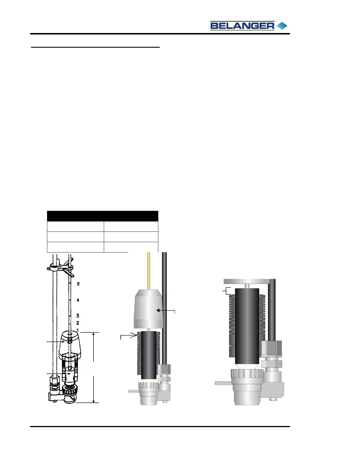
Float Cup Setting
The float cup is set by adjusting its height above the bottom of the brine valve assembly.
By removing the brine valve assembly and resting it on a flat surface, the height of the float cup can be
measured with a ruler. The height is measured from the base of the brine valve assembly to the top of the
float cup. See the image below.
Note that standard settings are defined by markings on the rod of the brine valve assembly. The settings on
the rod are listed in the tables at the end of this section.
Where the predefined settings are not adequate, the actual float cup height, in inches, is listed, and the setting
must be measured and set according to the measured float cup height.
Cut the first tab of the Brine Valve so 1.25 is the next tab. Set the Float at 10-1/2”.