INSTALLATION AND STARTUP
1MANUL220 Belanger, Inc.® * PO BOX 5470 * Northville, MI 48167-5470 * Ph (248) 349-7010 * Fax (248) 380-9681 6-5
Chapter 6 Treadle Assembly
Connections
The treadle has two electrical lines for proximity switches that require connection. Be sure that they are
properly wired according to your site-specific drawings.
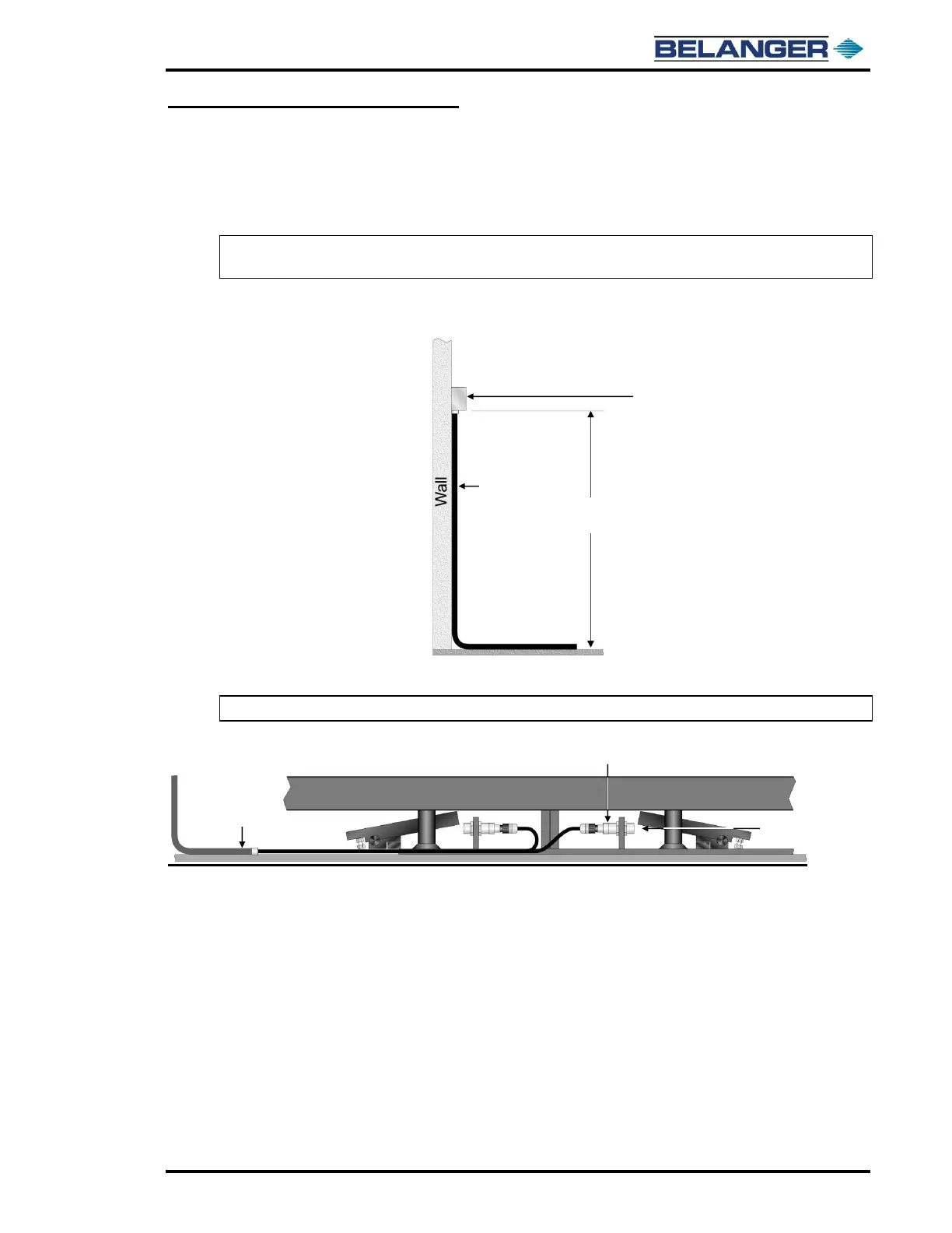
1) Mount the Treadle Junction Box to the wall on the same side as the Treadle Proximity Switches.
Note: Position the Junction Box at least 6 feet from the floor to prevent unnecessary exposure to
water and run conduit down the wall and over to the Treadle.
2) Feed the open end of the supplied cables up through the conduit and terminate them in the Junction Box and
to the SCC.
3) Connect the two Euro-Connectors to the Treadle Proximity Switches.
Note: Take care NOT to reverse the entrance and exit connections.