INSTALLATION AND STARTUP
1MANUL220 Belanger, Inc.® * PO BOX 5470 * Northville, MI 48167-5470 * Ph (248) 349-7010 * Fax (248) 380-9681 20-7
Chapter 20 Electrical
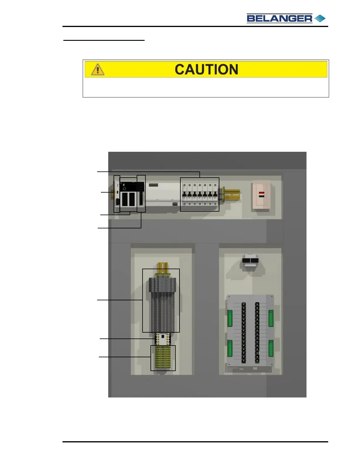
System Control Center (SCC) Panel
DO NOT punch ANY holes in the top of the enclosure. It may allow
moisture to leak inside. Doing so voids all warranties.
NOTE TO ELECTRICIANS AND ARCHITECTS
Use only CAT-5E stranded wire for communication between the System Control Center
(SCC) and the MCC. This communication wire is used to communicate with the Variable
Frequency Drives (VFD’s). Any extra wires in CAT-5E wire must not be used for other
circuits. CAT-5E wires must be installed to match colors of wire indicated in electrical
Prints.
The above image shows the components located inside of the System Control Center Enclosure
REFER TO YOUR SUPPLIED ELECTRICAL PRINTS, AND SITE-
SPECIFIC DRAWINGS FOR INSTALLATION DETAILS