INSTALLATION AND STARTUP
15-2 Belanger, Inc.® * PO BOX 5470 * Northville, MI 48167-5470 * Ph (248) 349-7010 * Fax (248) 380-9681 1MANUL220
Chapter 15 Wheel Cleaning and CTA Options
Wheel Stinger® and Chemical Tire Application (CTA) Options
Overview
Either of the Wheel Stinger® CTA options includes factory installation of the main manifold onto
the inside of the carriage. The remainder of the components will have to be installed in the field.
The next sections will assist in installing those components. See Nozzle Chart at the end of this
chapter for more details.
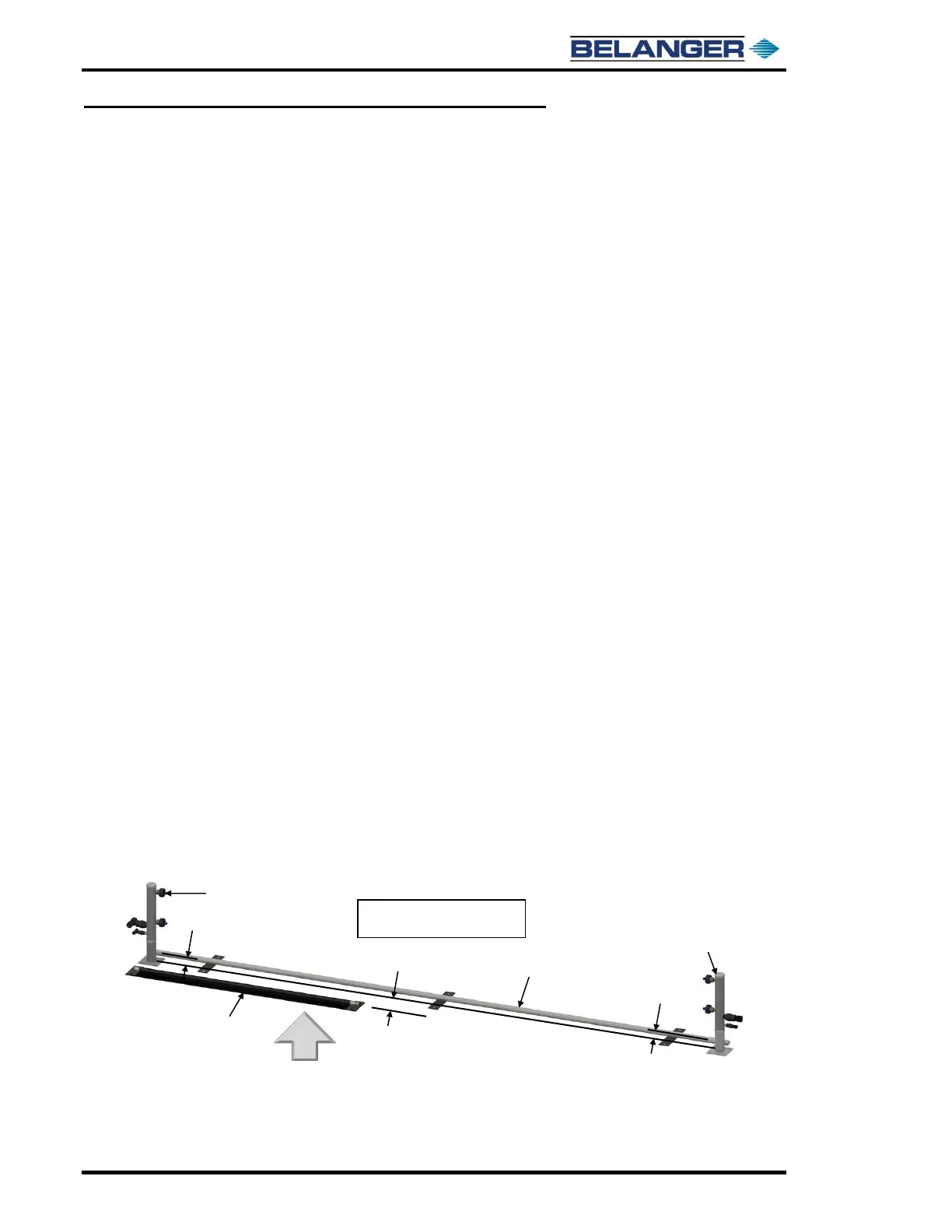
Wheel Stingers® and Freestanding CTA
See the image below and the Nozzle Chart at the end of the chapter for more details.
The Freestanding CTA has been designed to apply a consistently mixed solution onto the wheels
of a vehicle, as the vehicle travels through the wash. The recommended placement for a tunnel
application is after the enter switch and before a high-pressure rinse, allowing enough time for
the chemical to react. Dwell times will vary based on the type of chemical used, contact your
chemical supplier for dwell time guidelines.
The Primary applicator includes a 1/2” and 1/4” tee on the back of the manifold and should be
installed on the equipment room side of the bay. The secondary applicator should be positioned
across the bay in-line from the primary applicator. The tees on the primary applicator will deliver
the chemical/water mixture and air to the secondary applicator, using 1/4” and 1/2” poly-flow
tubing.
A cross over tube will be used in a drive-thru application to run the utilities from the primary
applicator to the secondary applicator. The center of the cross over tube should be positioned 3-
1/4” inches from the center of the applicators and will act as a speed bump slowing or stopping
the vehicle to allow the wheel of the vehicle to sit in the spray path to maximize coverage.
A Bell Hose style switch will be used to signal the input and turn on the applicators. The center
of the Bell Hose is to be installed 6” from the center of the applicators. The length of time chemical
is dispensed from the applicators is user defined and programmable from the electrical enclosure
on the pumping panel. An OFF delay timer inside the electrical enclosure must be adjusted to
match the line-speed or traveling speed of the vehicle in a drive-thru application.
The delivery panel has a 110-volt electric solenoid valve that will allow air flow to two regulators.
One regulator feeds the air pump that will deliver the premixed solution out to the applicators.
The other regulator will deliver compressed air to make the chemicals foam. A 1/2” poly-flow tube
will run from the outlet of the pump, and a 1/4” poly-flow line will run from the foam air regulator
on the delivery-pumping panel to the primary applicator. This system includes a reservoir. When
solution drops below the preset level the Hydro-minder float opens a non-electric magnetic valve.
The flow of water will siphon liquid concentrate into the water stream, automatically maintaining
the level of ready to use solution. The dilution ratio is adjusted with the metering tip selection
(orifice) that is installed into the siphon stub on the inductor body.