INSTALLATION AND STARTUP
1MANUL220 Belanger, Inc.® * PO BOX 5470. * Northville, MI 48167-5470 * Ph (248) 349-7010 * Fax (248) 380-9681 4-7
Chapter 4 Frame and Carriage Assembly
Carriage Prep
Once the carriage has been placed on the rails, it will need to be rolled from end to end to verify various system
operations and functions. The carriage can be moved “manually” or “electrically”. See the procedures below to
disengage the drive, raise the carriage or adjust the rails. See the procedure in Chapter 22 of this manual to move
the carriage “electrically.”
The following information is a recommended procedure to be carried out before the initial carriage installation. The following
procedures will allow you to roll the machine back and forth on the rails without having to fight with the drive system which is
tied into the drive gearbox. Since you will be able to roll the machine much more easily, the time it takes to properly space the
rails at both ends will be reduced. These procedures will also reduce the time it takes to set the right amount of slack for the
boom hoses at the machine side, the center of the boom arms, and at the boom wall mount weldment.
To prevent unwanted movement of the Carriage Assembly, it is locked into place by a steel key located in the Carriage
Gearbox. The following will instruct you how to disengage the Gearbox allowing free movement during the installation process.
Drive Shaft Disengagement
While the carriage is on the shipping frame the drive train can be disengaged from the gearbox allowing the carriage to
roll freely when mounted onto the rails. This movement allows ease during installation when verifying the expansion
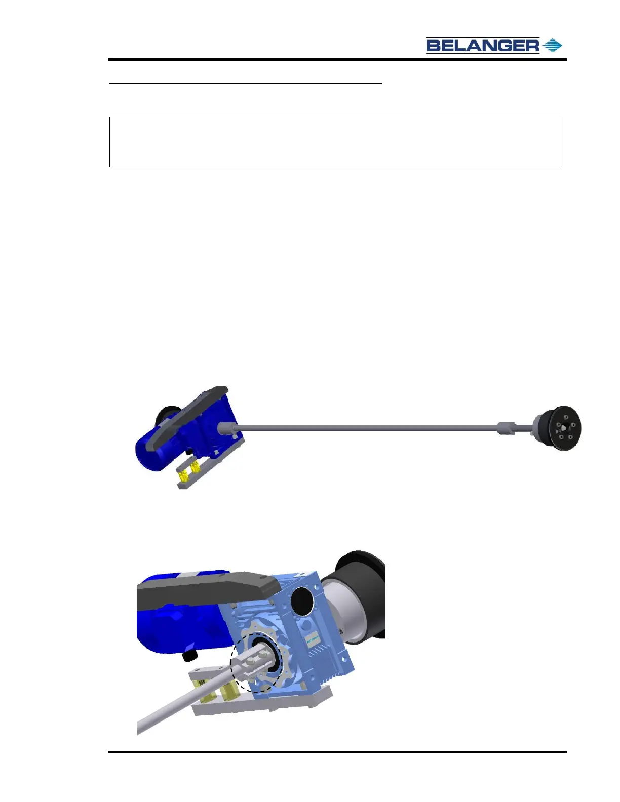
beam spacing, utility boom and boom mount operations. See the image below for an overview of the drive train.
Follow the steps below to properly disengage the drive train:
1) Locate the drive shaft coupling closest to the gearbox shown below.
Using a 9/16” open end wrench or ratchet with socket, loosen the coupling bolts.