INSTALLATION AND STARTUP
15-22 Belanger, Inc.® * PO BOX 5470 * Northville, MI 48167-5470 * Ph (248) 349-7010 * Fax (248) 380-9681 1MANUL220
Chapter 15 Wheel Cleaning and CTA Options
Cover Assembly
1) Locate the Wheel Stinger® Cover and the 9 sets of fasteners consisting of one of each of
the following: 1/4-20 x 1” stainless steel fastener, 1/4” stainless steel lock washer, 1/4”
stainless steel regular nut, and two 1/4” stainless steel flat washers.
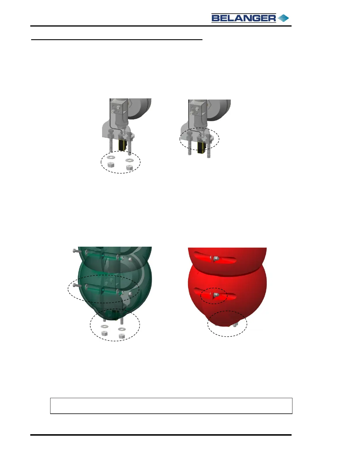
2) Remove the 2 sets of 1/2-13 center locking nuts and 1/2” flat washers on the Cover
Support Mount Assembly. See the image below.
3) Slide one half of the Stinger Cover up onto the 1/2-13 fastener protruding from the base
of the Wheel Stinger® Cover Support Mount.
Secure the cover half with the removed 1/2” flat washer and the center locking 1/2-13 nut.
See image below for close-up of both halves in place
• The final position of the nuts is just before the fastener threads would start
emerging from the other side, almost flush.
• Before moving on to the other half of the Wheel Stinger® Cover slide the crush
proof tubing down over the top of the secured Wheel Stinger® Cover so it will be
out of the way as you work on the other side.
4) Locate the other half of the Wheel Stinger® Cover and Repeat step 3.
5) With the 9 sets of 1/4-20 fasteners, nuts, and washers mate the two halves of the Wheel
Stinger® Cover together as shown above.
• The utility lines will not run directly behind the wheel cleaning manifold; this
would interfere with the cover. The lines will be tucked behind one of the cover
lips until emerging from the utility path.
Note: Be sure to position the tie wrapped utility lines to emerge from the utility path at the top of
Wheel Stinger® Cover as you mate the two together.