Chapter 22 Initial Startup
Check Inputs and Motion
Note: For the following checks, use the “Monitor Inputs” screen of the HMI (E-1063 Human
Machine Interface).
1) Check all inputs.
• Enter Door and Exit Door Photo-Eye
• Enter Load Photo-Eye
• Exit Load Photo-Eye
• All other installed Photo-Eyes
• Enter Load Sensor (Entrance Treadle Door)
• Exit load sensor (Exit Treadle Door)
• Carriage Encoder
Navigate to the JOG Screen on the HMI (E-1063 Human Machine
Interface).
Press CARRIAGE BACKWARD and verify that the machine moves
towards the entrance of the bay. If it moves the wrong way, swap your
motor leads at the MCC.
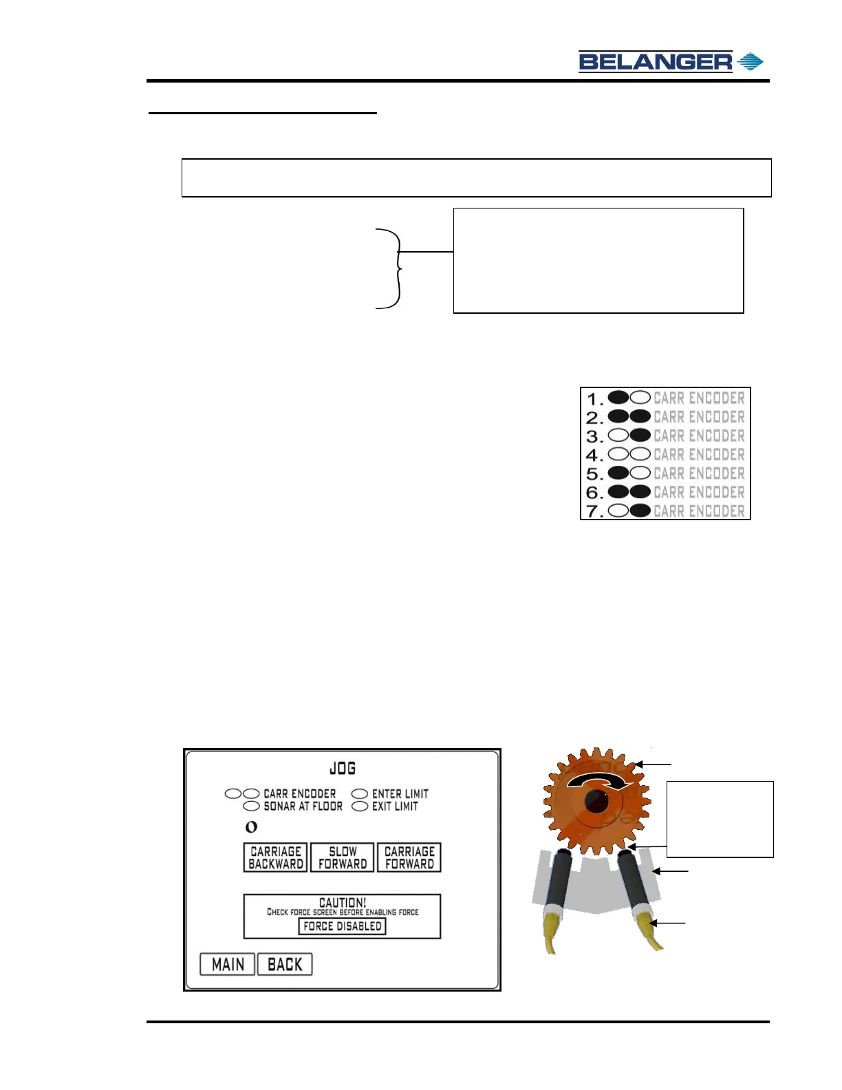
Press SLOW FORWARD while watching the CARR ENCODER
ovals. The oval pattern should move left-to-right while the machine is
moving slowly forward (see example at right). If the oval pattern
moves right-to-left, swap the Encoder Prox wires at the proximity
switches.
Encoder Proximity Switch Gap
Slow Forward: has been provided to check proper carriage Encoder operation.
Pressing the Slow Forward button first begins the Carriage moving slowly down the rails causing the gear in the
Encoder to turn. The ovals next to “CARR ENCODER” fill from left to right and clear from left to right.
If the oval fill/clear pattern is not according to the above, first check wiring. A typical fix if pattern is reversed is to swap
Proximity Cables on the Encoder.
Pressing and holding the SLOW FWD button will cause the display to appear for A and B Phase Encoder on times.
The proximity sensors should be adjusted until these are nearly identical.
Target Gap Distance will show on the HMI (E-1063 Human Machine Interface) Jog Screen. If needed make
adjustments by moving the Proximity Switch “IN” or “OUT” until the gap distance numbers below are achieved.
Remember to Push in the Emergency Stop Button if you are going into the Carriage to make adjustments!