INSTALLATION AND STARTUP
1MANUL220 Belanger, Inc.® * PO BOX 5470. * Northville, MI 48167-5470 * Ph (248) 349-7010 * Fax (248) 380-9681 14-15
Chapter 14 HydroBlade® Assembly Option
HydroBlade® Rinse Quick-Dump Assembly – Installation
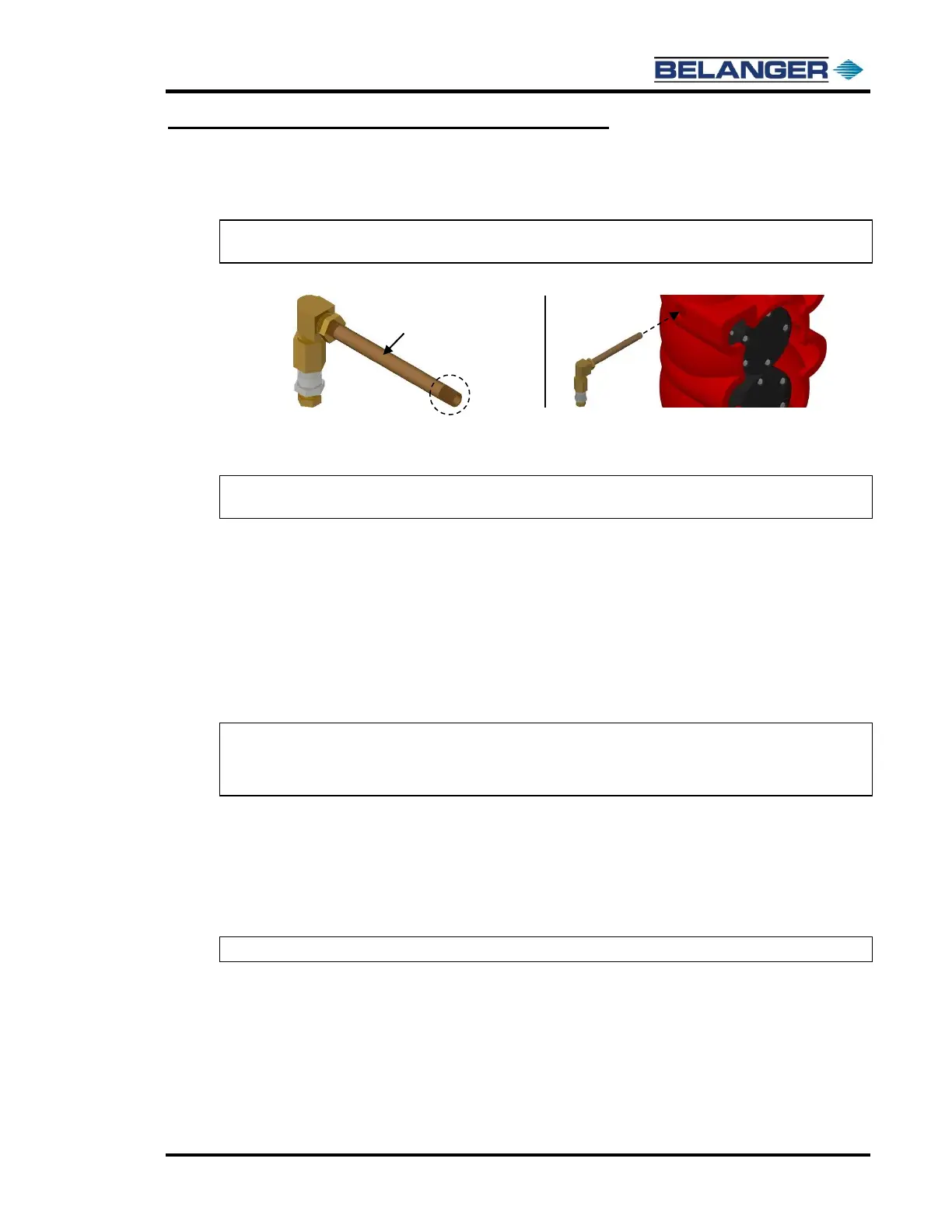
3) Apply Teflon™ tape and liquid Teflon™ to the threads of the brass 6” nipple and screw the HydroBlade®
Quick Dump Assemblies into place. See the image below.
Note: Make sure that the assemblies are both facing downward when they are tightened. See the
image below.
4) When you run your first test wash verify that water does not come out of the drain hole while the
HydroBlade® is in operation.
Note: Once the HydroBlade® operation is complete it may take a second or two for the water to
begin to drain out.
Setting up the Pumping Station and Running the Utilities
Remove the Pump Station from the packaging crate, position it into its final location and lag it to the floor. The utilities
that are necessary depend on the pumping station purchased. Follow the steps that apply to your site.
10HP Pumping Station
See the Nozzle Chart on the next page.
25HP Pump
1) Run a field supplied 3/4" hose from the pumping station to the Lexair™ manifold inside the carriage.
Note: The specifications of this line require a minimum rating of 1500 psi and a minimum bend
radius of 8’’.
Note: Keep this line as short as possible to limit losses that occur in long hose runs.
2) Run the field supplied 3/4” hydraulic line with the above specifications from the outlet of the pumping station
up along the entrance side of the boom
Attach the line using ALL 6 of the supplied Stauff™ clamps so that when the high-pressure kicks on it cannot
cause the hose to jump around and wear out.
Run the line through the smallest window on the utility hose support.
Tighten the line onto the Lexair™ manifold.
Note: See Routing Boom Utilities in Chapter 6 for further details.