EasyManua.ls Logo

Belanger FreeStyler - Wiring

Belanger FreeStyler
321 pages
Print Icon
To Next Page IconTo Next Page
To Previous Page IconTo Previous Page
Loading...
INSTALLATION AND STARTUP
5-4 Belanger, Inc.® * PO BOX 5470. * Northville, MI 48167-5470 * Ph (248) 349-7010 * Fax (248) 380-9681 1MANUL220
Chapter 5 Entrance and Exit Photo-Eyes
General
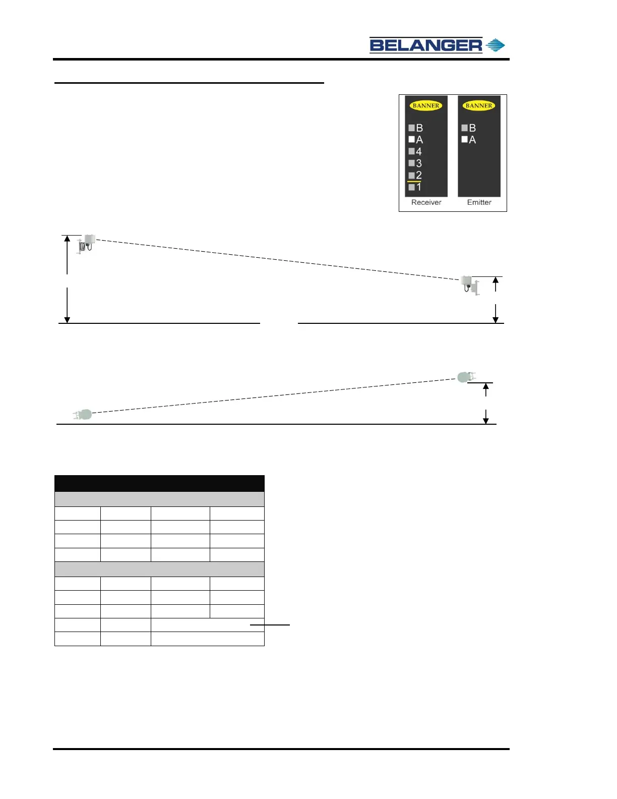
Modulation Frequency
The standard configuration for Photo Eyes is to utilize Frequency A (shown in the
image to right). However, if a system installation has the possibility for “Photo Eye
Cross-Talk”, the affected Photo Eye set may be configured to utilize Frequency B. In
the case of “Photo Eye Crosstalk” both Emitter and Receiver must be wired for
Frequency B.
View from Bay Entrance
View from Overhead
Wiring
Wiring for the Vector QS30
Emitter
Brown
#340
24VDC
Blue
# 338
0VDC
Gray
# 340
24VDC
White
No Connection
Receiver
Brown
#340
24VDC
Blue
# 338
0VDC
Gray
# 340
24VDC
White
FreeStyler® Input X30 X35
Black
No Connection
If the Wall Mounted configuration is used, mount the Photo Eyes at the heights indicated.
33”
16”
Receiver
Emitter
6”
Mount the Photo Eyes with a minimum of 6” offset.
Receiver
Emitter
Floor
Reference Sheet 4 of the Electrical Schematics.
Actual input wire numbers can vary by site.

Table of Contents

Related product manuals