INSTALLATION AND STARTUP
1MANUL220 Belanger, Inc.® * PO BOX 5470. * Northville, MI 48167-5470 * Ph (248) 349-7010 * Fax (248) 380-9681 4-3
Chapter 4 Frame and Carriage Assembly
Floor Mounted Frame
If the bay walls are less than 192” apart, cut both Head beams 2” shorter than the wall spacing. Mark the
new Head beams centerlines considering the machine position according to the “Position Consideration
Chart” in Chapter 3.
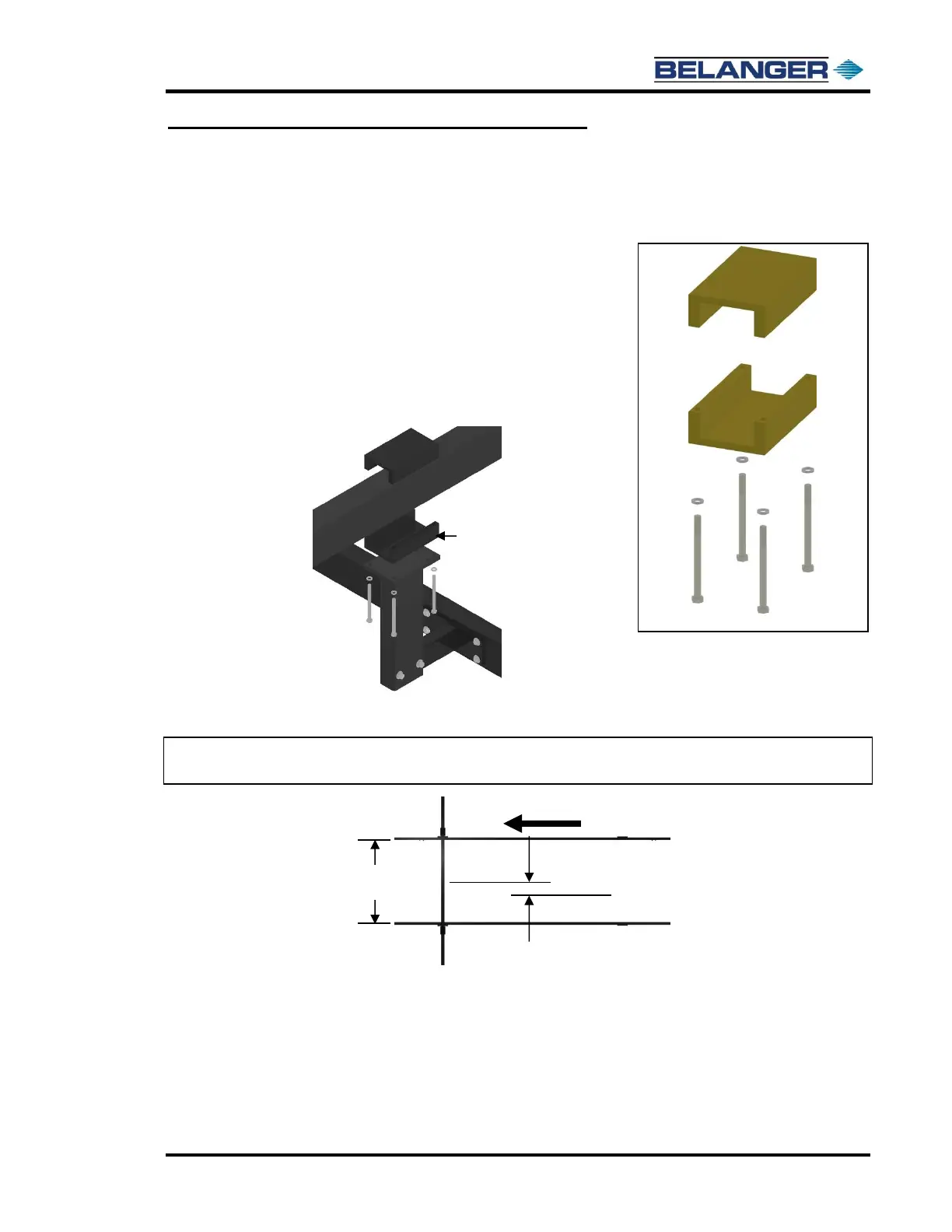
7) Locate two of the four head beam clamps and take them apart.
Place the non-threaded sides on top of the two L-Brackets.
Place the other half of the clamp on top of the head beam
and start the bolts.
Tighten the passenger side bracket bolts down “all the
way” at the location 46-1/8” from inside of the rail to the
Head beam centerline.
Repeat the above steps on the exit end Head Beams and
Clamps. See assembled image below.
Check the rail spacing once more and tighten the driver’s side head beam clamps down
completely.
Note: If the spacing needs to be spread to 100’’, follow on to Step 8; if it does not need to
be separated, skip to Step 9.
8) Once the driver side head beam clamp assemblies are completely tight, loosen the bolts until the
lock washers are no longer compressed.