INSTALLATION AND STARTUP
5-2 Belanger, Inc.® * PO BOX 5470. * Northville, MI 48167-5470 * Ph (248) 349-7010 * Fax (248) 380-9681 1MANUL220
Chapter 5 Entrance and Exit Photo-Eyes
Photo-Eye Layout and Description
Two sets of Photo-Eyes will typically cover all FreeStyler® functions and options.
More sets can be added to the system in the case where a customer desires precise on/off timing for
particular components such as a free-standing Pre-Soak or other out-board free-standing pieces of
equipment. The system can accommodate up to 5 sets total (3 sets at the entrance and 2 sets at the
exit).
Before installing any of the Photo-Eyes, read and understand the Entrance Operations and Exit
Operations sections from the FreeStyler® Programming Manual.
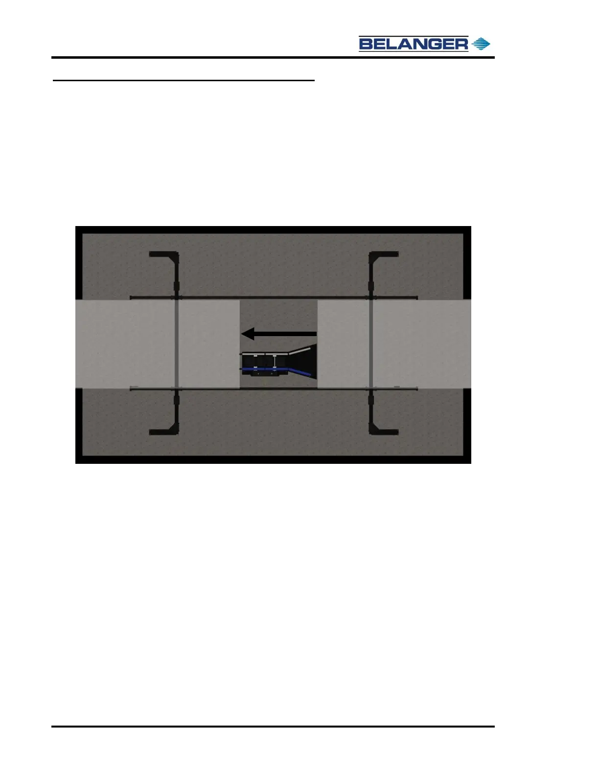
The image below shows the “zones” that are assigned to a two Photo-Eye set system.
The “Entrance Zone” is typically between the entrance Photo-Eyes and just after the treadle. Equipment
in this zone typically turned on with the Photo-Eye, and then turned off by either the Photo-Eye or the
Treadle even though other on/off options are available.
The “Exit Zone” is typically between the Treadle and the exit door Photo-Eyes. Equipment in this zone
is typically turned on at END OF CYCLE and then turned off when past the Photo-Eyes. Many other
on/off options are available.
The actual installation of the Photo-Eyes is covered later in this document.