INSTALLATION AND STARTUP
1MANUL220 Belanger, Inc.® * PO BOX 5470. * Northville, MI 48167-5470 * Ph (248) 349-7010 * Fax (248) 380-9681 14-11
Chapter 14 HydroBlade® Assembly Option
HydroBlade® R.O. / Low Pressure Feed Assembly
Installation
6) Remove the 1/2” other half of the blue water hose that was removed in Step 4. It is located in the brass elbow that
on the top of the brass cross. See the image above in Step 4.
Replace the brass elbow in the cross with a field supplied 1/2” plug.
Shut the pod cover door when complete.
7) Repeat Steps 5 and 6 for the Driver side of the machine.
Note: The HydroBlade® Low Pressure Feed Kit Assembly and the HydroBlade® Feed Assembly
are both located near the center of the carriage just above the Universal Manifold. Step 8
involves the upper manifold, the HydroBlade® Low Pressure Feed Assembly.
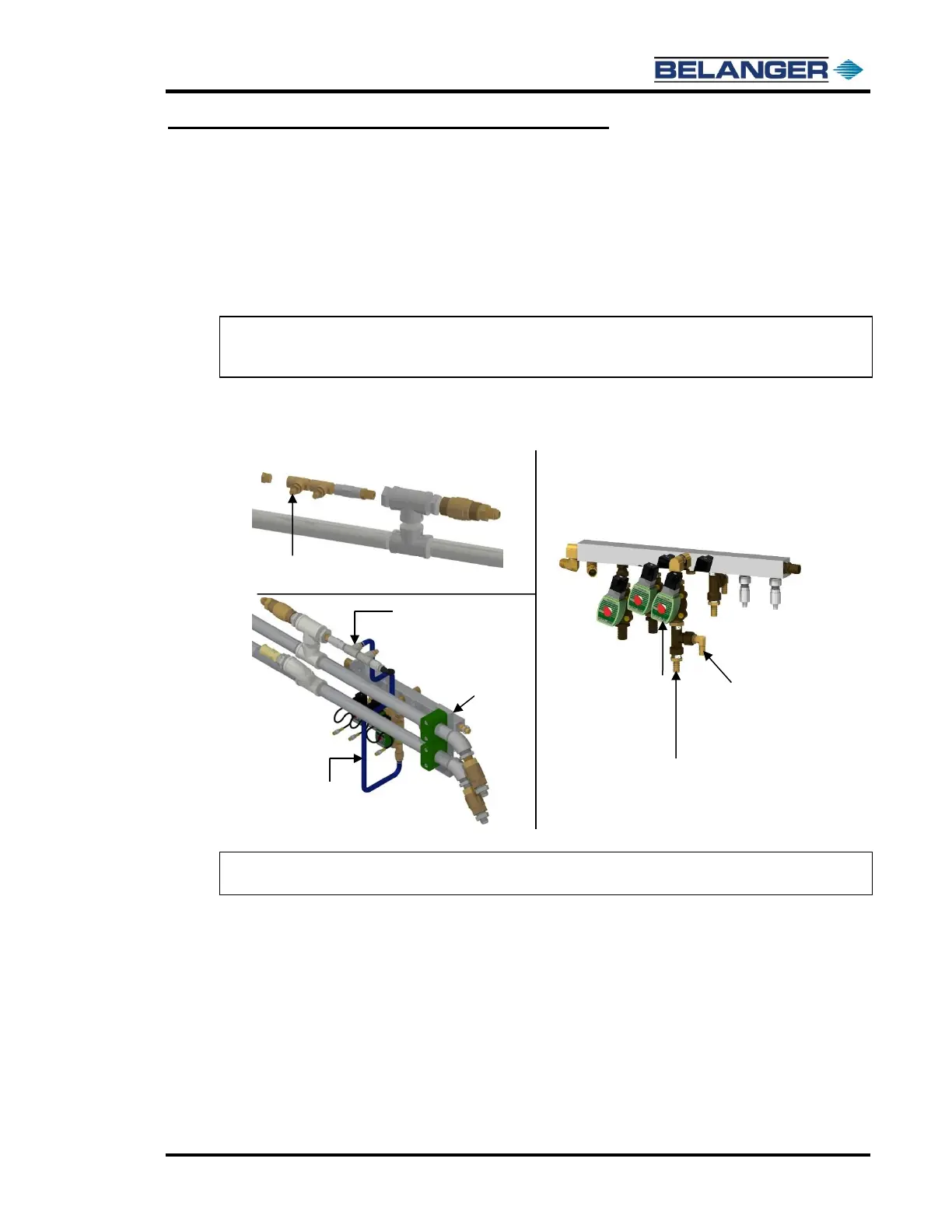
8) Place two field supplied 1/2” ear clamps on a length of blue water hose
Run the hose from the inner most brass fitting in the HydroBlade® Low Pressure Feed Kit to the straight
fitting that is in the tee on bottom of the RO Asco™ valve in the Universal Manifold. See the images below.
9) Crimp both clamps once the hose has been cut to the proper length and secured into place.
Note: Be sure that the hose is not positioned in a way that it will be cut or crimped by the machines
operating motion.
10) Remove the brass elbow from the brass tee on the bottom of the RO Asco™ valve on the Universal Manifold and
replace it with a field supplied 1/2” plug. See the image above in Step 8.
11) Shut the exit Utility Cover.
Power up the machine.
Run a test wash to verify that there are no leaks and that all connections are tight.
See Nozzle Chart later in this chapter for more details.