INSTALLATION AND STARTUP
1MANUL220 Belanger, Inc.® * PO BOX 5470 * Northville, MI 48167-5470 * Ph (248) 349-7010 * Fax (248) 380-9681 20-9
Chapter 20 Electrical
E-1063 Operator Interface
THE MODEM AND THE CUSTOMER INTERFACE DEVICE (POINT OF SALE UNIT)
MUST USE 2 SEPARATE DEDICATED ANALOG TELEPHONE LINES.
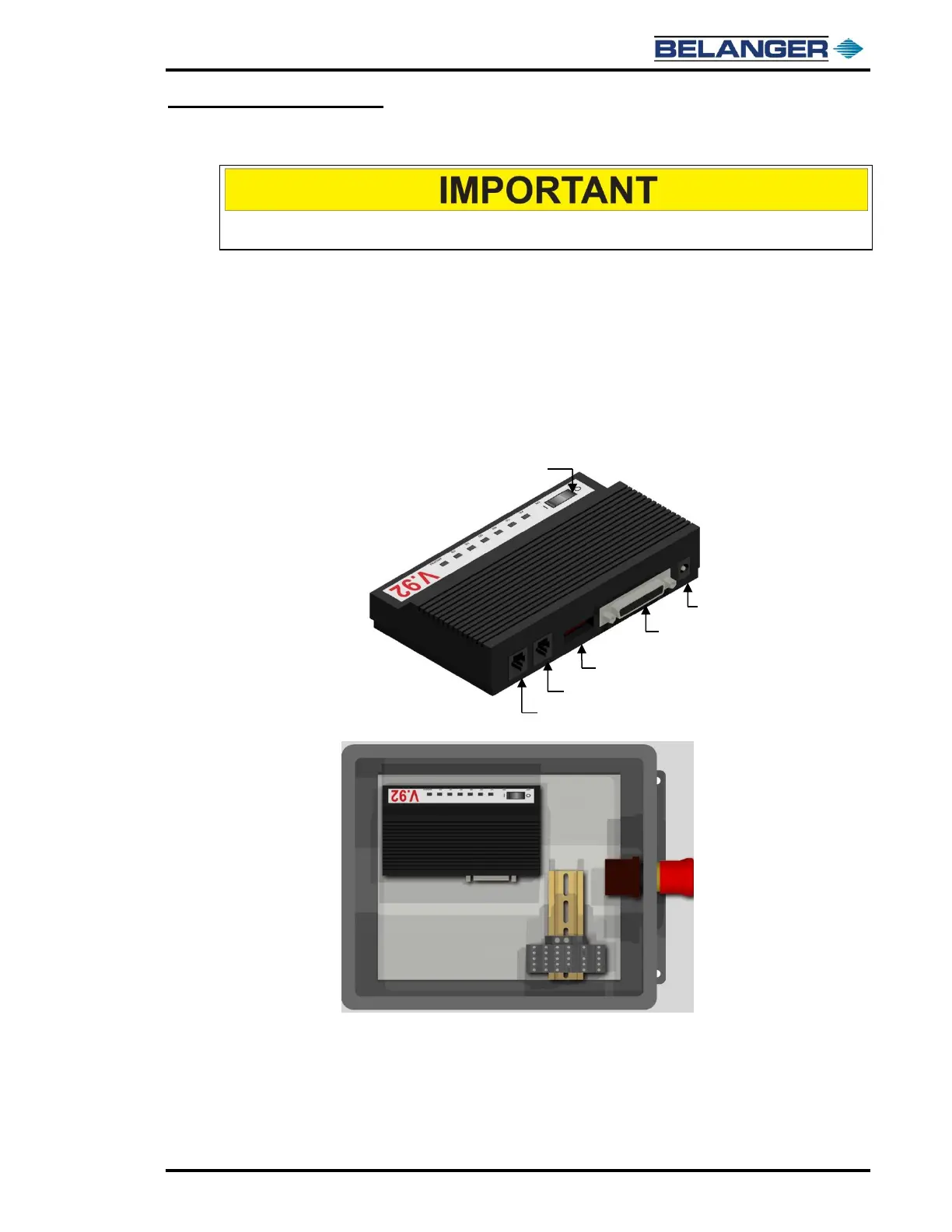
Modem Overview
Typically, a single bay FreeStyler® system requires (1) DEDICATED analog telephone line with
an RJ-11 Connector terminal inside the E-1063 enclosure.
If you purchase a customer interface device that has credit card capability, you will require a
SECOND DEDICATED line for its use. These two items will NOT work well on a single line.
Installation
The installation contractor should provide a standard RJ-11 plug-in jack next to the E-1063 from
the same dedicated line serving the Modem for use in plugging in a telephone.
The above image shows the components located inside of the FreeStyler® E-1063 HMI (Human Machine Interface) Enclosure
REFER TO YOUR SUPPLIED ELECTRICAL PRINTS, AND
SITE SPECIFIC DRAWINGS FOR INSTALLATION DETAI