INSTALLATION AND STARTUP
1MANUL220 Belanger, Inc.® * PO BOX 5470. * Northville, MI 48167-5470 * Ph (248) 349-7010 * Fax (248) 380-9681 3-5
Chapter 3 Getting Started
Installation Overview
Length Considerations
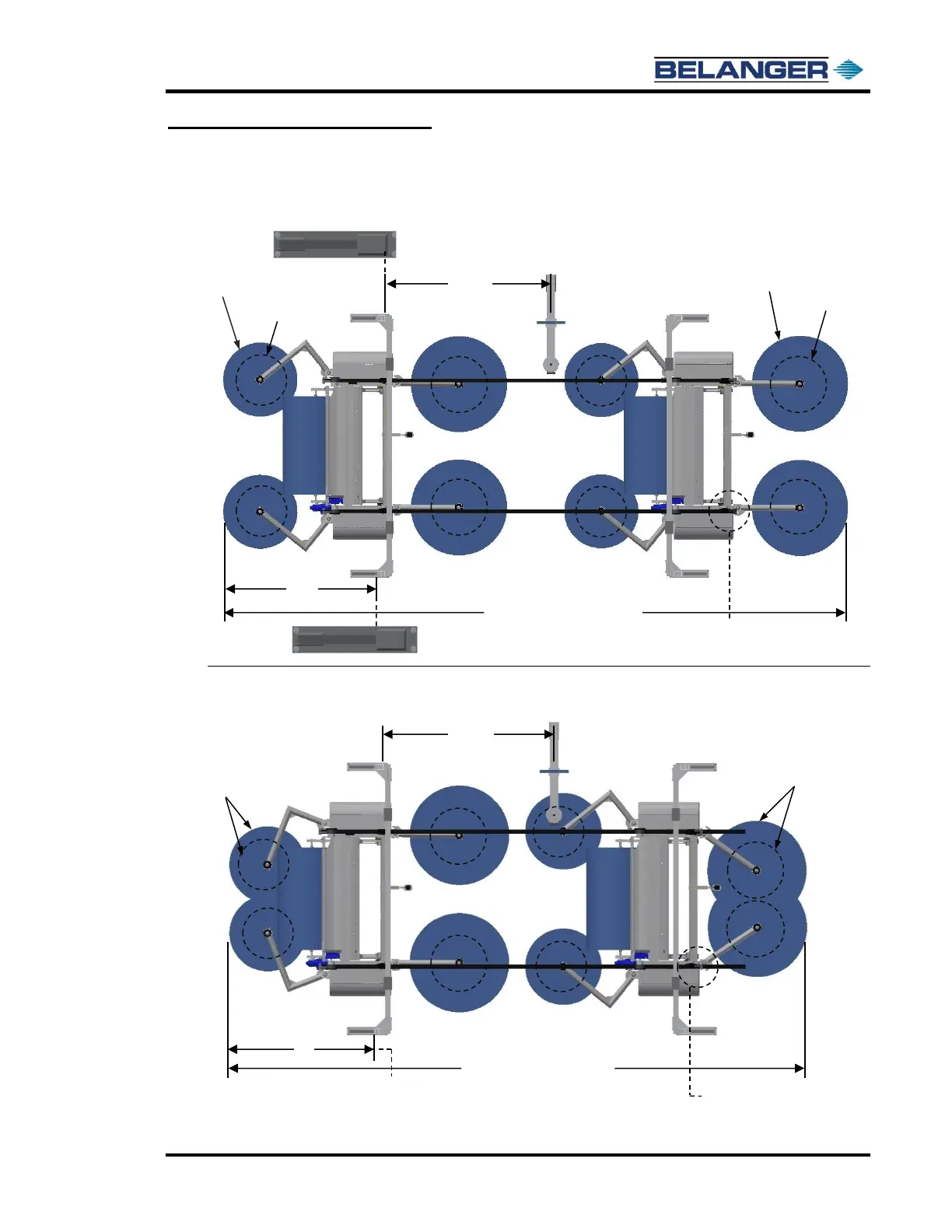
Square 4-Legged Frame: Configuration #2 Standard Bay Length (34-6” bay)
Square 4-Legged Frame: Configuration #2 Small Bay Length (32’-0” bay)
6-Legged version of this configuration shown later in this section
Positive Stop Clamps
Moved In 30”
This dimension taken from
center of Boom Mount
21’ – 9” Vehicle Conditions:
Small Bay Software (34’-6”)
Wheels begin spinning in this position
Machine
Entrance
Position
Machine
Entrance
Position
This dimension taken from
center of Boom Mount
See top image for origin of where
the 92” dimension is taken from
The 106” dimension is taken
from the exit edge of the leg
The 124-1/2” dimension taken from
entrance side edge of exit leg
See top image for origin of where the
124-1/2” dimension is taken from
Position of the Positive Stop
Clamps will be determined by
the bay length
21’ – 9” Vehicle Conditions:
Long Bay Software (37’-0” feet)
Wheels begin spinning in this position
70” Diameter
when Spinning
45” Diameter
when Spinning
54” Diameter
when Spinning
39” Diameter
when Spinning
See top image for diameter of
wheels when spinning
See top image for diameter of
wheels when spinning