INSTALLATION AND STARTUP
1MANUL220 Belanger, Inc.® * PO BOX 5470. * Northville, MI 48167-5470 * Ph (248) 349-7010 * Fax (248) 380-9681 4-13
Chapter 4 Frame and Carriage Assembly
Rail Travel Stop-Clamp Placement
Note: With the drive shaft key still removed, you should be able to push the carriage down the rails
by hand from stop-to-stop.
2) Check for binding and adjust the rail width as necessary to maintain clearance from the inner and
outer lips of the carriage Rollers.
Note: The clearance between each roller and the side of the rail at the center of each detail plate
should be checked and verified to be around 1/16’’.
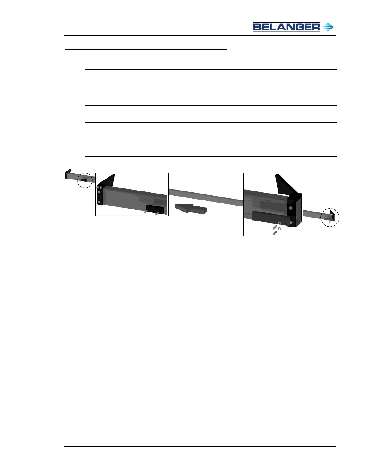
3) Install End Limit Proximity Targets on the passenger side rails as shown below.
Note: The entrance target installs on the Rail Travel Stop Clamps.
Note: The exit target installs onto the rails.