INSTALLATION AND STARTUP
4-32 Belanger, Inc.® * PO BOX 5470. * Northville, MI 48167-5470 * Ph (248) 349-7010 * Fax (248) 380-9681 1MANUL220
Chapter 4 Frame and Carriage Assembly
Connecting the Standard Boom Channel
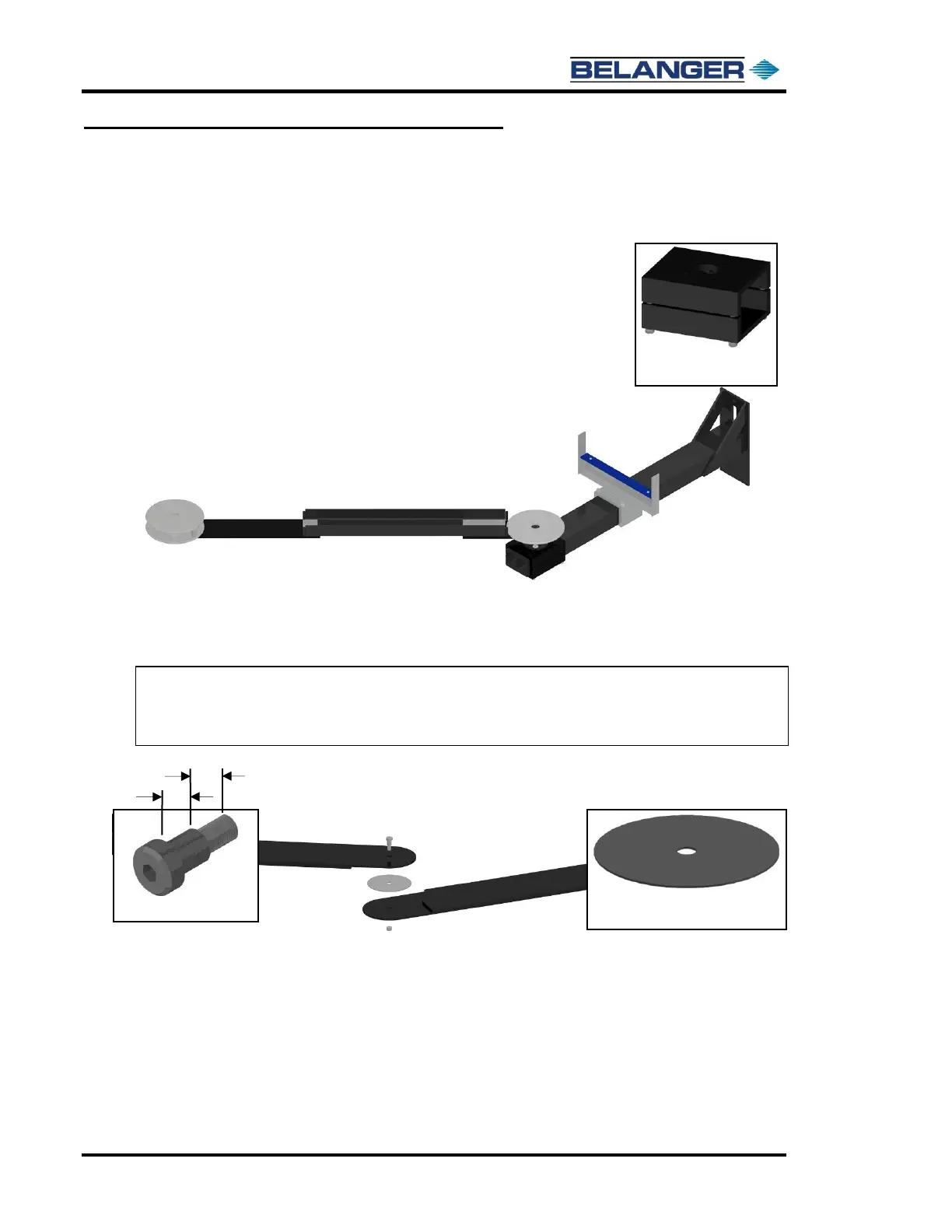
3) Locate the second Wall Mount Boom Arm Assembly, the Boom Mount Clamps, the supplied 1/2-
13 x 3-1/2” fasteners, and the 1/2” stainless steel lock washers.
Attach the Boom Arm to the Boom Wall or Freestanding Mount Leg as shown below.
4) Locate the Boom Linkage Wear Washer, the supplied 1/2 x 5/8” stainless steel shoulder bolt, and
the 3/8-16 stainless steel Nylock™ nut.
Place the wear washer in between both linkage arms and tighten in place with the shoulder
bolt and Nylock™ nut as shown below.
Note: The Nylock™ nut should tighten to the shoulder bolt only and should not compress the
Linkage Arms. If the Linkage Arms do compress together, remove the bolt and check the
length to be sure it is correct. It should have no more than 3/8” of thread length and 5/8” of
shoulder length. See the images below.