Parameter descriptions
7.3.3 Stopping behavior
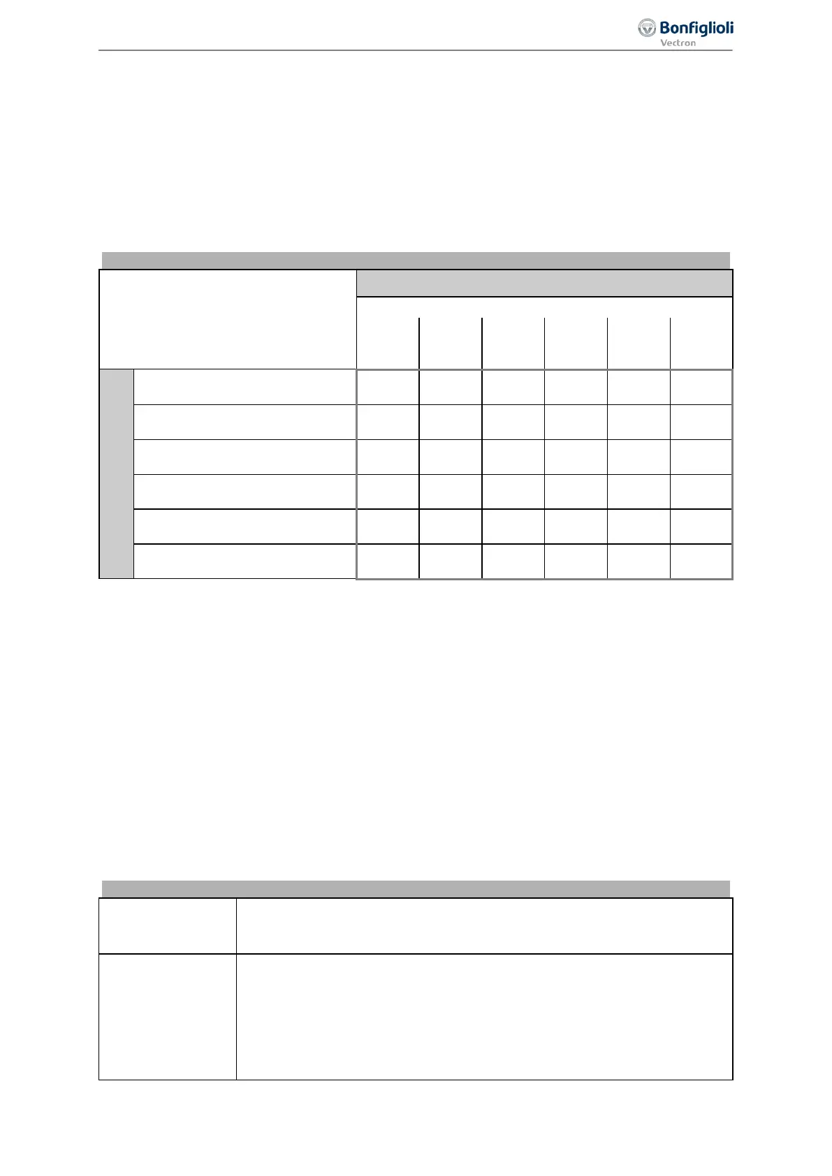
630 Operation mode (P68&P69=1 | P68&P69=0)
The stopping behavior can be defined via parameter
Operation mode (P68&P69=1 |
P68&P69=0)
630. The signal states of the digital inputs or logic signals for parameters Start clock-
wise
68 and Start anticlockwise 69 activate the stopping procedure. Digital inputs or logic signals can
be assigned to these parameters. In the factory settings,
Start clockwise 68 is assigned "71 - IN1D"
(terminal X11.4) and
Start anticlockwise 69 is assigned "72 - IN2D" (terminal X11.5). By combination
of the digital input states or logic signals, the stopping behaviors can be selected from the following
table.
Operation mode Stopping behavior
Operation mode (P68&P69=1 |
P68&P69=0)
630
Start clockwise = 0 and Start anticlockwise = 0
Stopping behaviour (refer to table “Stopping behavior)
0 1 2 4 5 7
Start clockwise = 1 and
Start anticlockwise = 1
Stopping behavior 0
(Coast to Stop)
0 1 2 4 5 7
Stopping behavior 1
(Stop and switch off)
10 11 12 14 15 17
Stopping behavior 2
(Stop and hold)
20 21 22 24 25 27
Stopping behavior 4
(Emergency stop and switch off)
40 41 42 44 45 47
Stopping behavior 5
(Emergency stop and hold)
50 51 52 54 55 57
Stopping behavior 7
(DC brake)
70 71 72 74 75 77
Operation mode 630 of the stopping behavior is to be parameterized according to the matrix. The
selection of the operation modes can vary according to the control method and the available control
inputs.
Example:
The motor is to stop according to stopping behavior 1 if the digital logic signals
Start Clockwise 68 =
1 and
Start Anticlockwise 69 = 1.
Additionally, the motor is to stop according to stopping behavior 2 if the digital logic signals
Start
Clockwise
68 = 0 and Start Anticlockwise 69 = 0.
To achieve this, the value 12 (Stop, Off | Stop, Hold) must be set for parameter
Operation mode
(P68&P69=1 | P68&P69=0)
630.
By selecting the stopping behavior you also select the control of a mechanical brake if operation mode
"41-Open brake" is used for one digital output for controlling the brake.
Stopping behavior 0
Coast to Stop
The inverter is disabled immediately. The drive deenergized immediately and
coasts freely.
Stopping behavior 1
Stop and Switch off
The drive is brought to a standstill at the set deceleration. As soon as the
drive is at a standstill, the inverter is disabled after a after a holding time. The
holding time can be set via the parameter
Holding time stop function 638.
Depending on the setting of the parameter
Operation mode 620 the Starting
current
623 is impressed or the Starting voltage 600 is applied for the dura-
tion of the holding time.
127
Operational Behavior 06/2013 Operating Instructions
Agile

 Loading...


