Electrical Installation
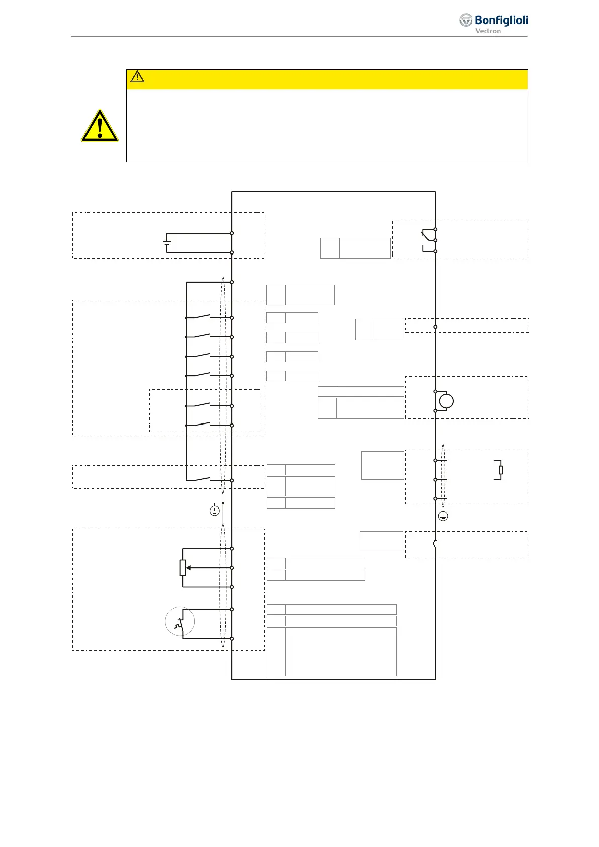
5.7 Control terminals Standard connection
CAUTION
The unit may only be connected with the power supply switched off.
Verify that the frequency inverter is discharged.
Switch off power supply before connecting or disconnecting the control inputs and out-
puts. Verify that the keyed control inputs and outputs are deenergized before connect-
ing or disconnecting them. Otherwise, components may be damaged.
Comply with the technical data of control terminals: See chapter 11.3 "Control electronics".
For evaluation of the motor thermo contact, parameter
Operation Mode Motor-PTC 570 must be set.
See Chapter 7.4.6 "Motor temperature“.
Via parameters
Digital inputs PNP/NPN 559, the logic evaluation at IN1D, IN2D, IN4D and IN5D is
changed.
STOA
X11.3
STOB
X13.3
Digital inputs
Factory settings
Multi-function inputs
Enable
X11.4
Start Clockwise
IN1D
Start Anticlockwise
IN2D
X11.5
X11.6
IN3D
Data Set Change-Over 1
X12.1
IN4D
Fixed Frequency
Change-Over 1
X12.2
IN5D
Error Acknowledgment
MFI1
X12.3
MFI2
X12.4
Digital Input/Output
Motor thermal contact
°C
M
X11.2
X11.1
Output
24 VDC
Output
10 VDC
X13.4
X13.2
Reference speed
Cable shielding
GND
0 ... 10 VDC
U = 30 VDC
max
I
max
= 1 A
15 ... 30 VDC, I = 100 mA
max
240 VAC or 24 VDC
U = 30 VDC
max
Digital output
Relay output
OUT1D
OUT2D
X13.5
X10.1
X10.2
X10.3
MFO1
X13.6
Multi-function output
X13.2
GND
GND
V
+
GND
Bus termination
U proportional to
actual frequency
Run Signal
Error Signal
X13.1
X13.2
External power supply (optional)
Input
24 VDC ±10%
P562 3-Digital NPN (active: 0 V)
P204
532-MFI2D (HW)
P550
10-Analog MFO1A
P553
7-Absolute value
Actual frequency
P558
0-Input IN3D
P559
1-PNP
(active: 24 V)
P559
1-PNP
(active: 24 V)
P570
0
1
2
3
Off
Thermal contact, P204:
Warning only
Thermal contact, P204:
Error switch-off
Thermal contact, P204:
Error switch-off 1 min delayed
P452 1-Voltage 0...10 V
P475
1-Analog value MFI1A
P533
103-Inv. Error
Signal
P70
73-IN3D
P531
2-Run
signal
CANopen or
CAN system bus
X12.5
X12.6
RJ45
RS485
CAN H
CAN L
Modbus or VABus
P276
Terminals:
System bus
P395
X21: VABus
P68
71-IN1D
P69
72-IN2D
P66
74-IN4D
P103
75-IN5D
X21
GND CAN GND
43
Control terminals Standard connection 06/2013 Operating Instructions
Agile

 Loading...


