Parameter descriptions
7.3 Operational Behavior
The operational behavior of the frequency inverter can be adjusted to the application by setting the
parameters appropriately. In particular the acceleration and deceleration behavior can be selected
according to the selected
Configuration 30. Additionally, features such as Auto Start, and the syn-
chronization and positioning functions facilitate the integration in the application.
7.3.1 Control
The frequency inverters are suitable for data communication and can be extended by communication
modules. In this way, they can be integrated in an automation and control system. Parameterization
and commissioning can be done via the operator panel or a communication interface.
Control can be done via contacts, keypad on the operator panel or communication interface.
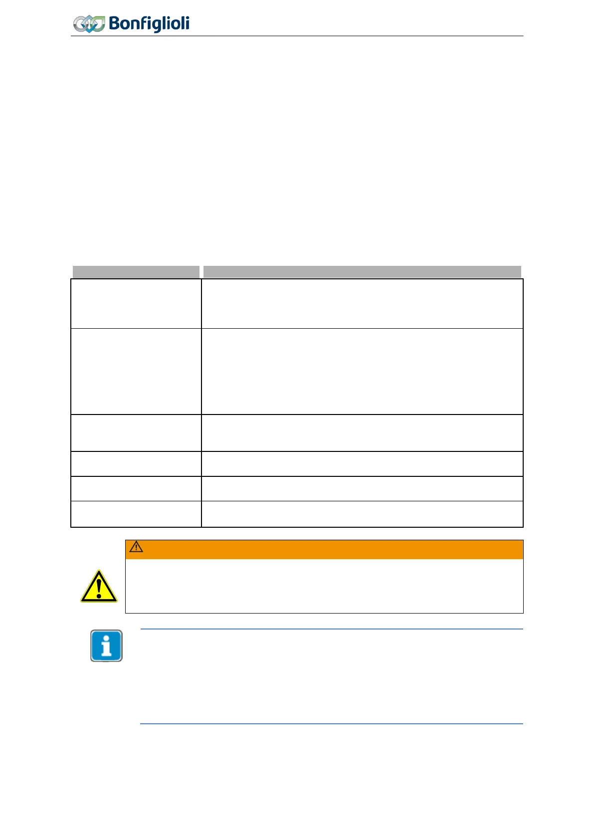
412 Local/Remote
Parameter
Local/Remote 412 defines the command sources for start, stop and direction of rotation
are to be issued. The parameter enables choosing from control via contacts, operator panel or com-
munication interface.
0 - Control via Contacts
The commands start and stop as well as the definition of the direction
of rotation (parameters Start Clockwise 68, Start Anticlockwise 69)
are issued via digital inputs. Run, Stop and Reset commands from the
1 -
Control via Statema-
chine
The Start and Stop commands as well as the direction of rotation are
controlled via the Remote Statemachine of the communication inter-
face. The control is done via the Controlword, which can be monitored
via 410
Controlword or which can be used to simulate it. With 411
Statusword the state of the drive can be monitored. The statusword is
typically sent to the overlying control (PLC). Run, Stop and Reset
commands from the keypad keys are ignored.
2 -
Control via Remote-
Contacts
The Start and Stop commands as well as the direction of rotation are
controlled via logic signals through the communication protocol. Run,
Stop and Reset commands from the keypad keys are ignored.
3 - Control via Keypad
The start and stop commands as well as the direction of rotation are
entered via the operator panel.
4 -
Control via Keypad or
Cont.
The start and stop commands as well as the direction of rotation are
entered via the operator panel or via digital inputs. Factory setting.
5 - Control 3-Wire
Control of direction of rotation (parameters Start Clockwise 68, Start
Anticlockwise
69) and signal
87 via digital inputs.
WARNING
If the operation mode is changed while the drive is running, the drive will not be
stopped if no stop command is present in the new operation mode.
In
order to be able to control the drive, the output stage must be enabled by digital
inputs STOA and STOB.
Signals via physical contacts (IN1D…IN5D, MFI1, MFI2) are only evaluated if an oper-
ation mode with “Control via Contact” or “Control 3
-Wire” (0, 4 or 5) is selected.
In all other operation modes (1, 2, 3) physical contacts are only evaluated, if the cor-
responding signals in the digital inputs with the suffix (Hardware) are selected. Please
comply with chapter
7.6.6 “Digital inputs”.
Signals not referring to a physical input are evaluated independent of the operation
mode
Local/Remote 412.
122
Operating Instructions
Agile
06/2013 Operational Behavior

 Loading...


