Home
BONFIGLIOLI
DC Drives
Agile
BONFIGLIOLI Agile User Manual
4
of 1
of 1 rating
360 pages
Give review
Manual
Specs
To Next Page
To Next Page
To Previous Page
To Previous Page
Loading...
Options
12.9.1.4
Size 3 (5.5 kW to 11.0 kW)
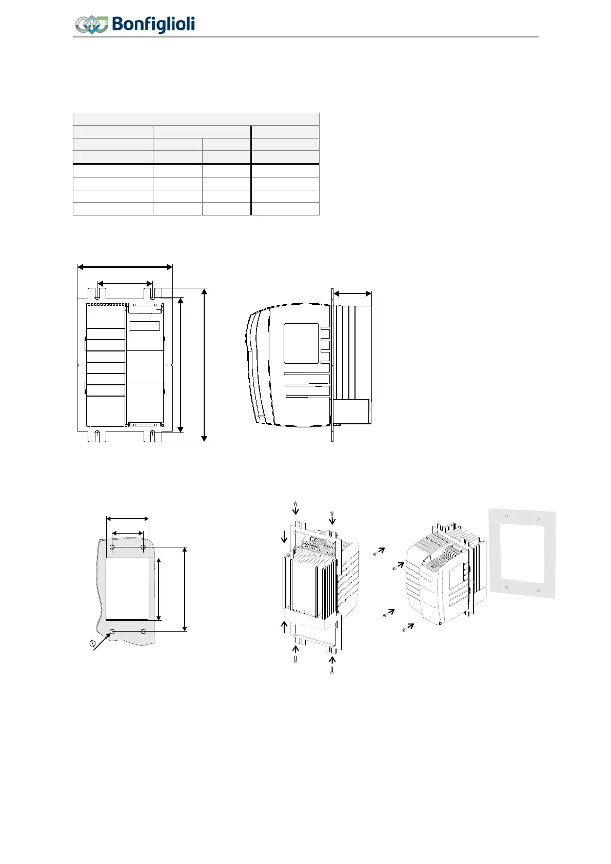
12.9.1.4.1
With he
at sink fan
Valid for the following devices
Frequency inverter
Typ
e
Agile
2
02
Agile
402
Mains supply
1ph.
3ph.
3ph.
Power
kW
kW
kW
-
19
3
3
5.5
5.5
-
21
3
3
7.5
7.5
-
22
3
--
--
9.2
-
23
3
--
--
11
Place a seal between frequency inverter and mounting plate.
Use screws M6 with minimum length 30 mm.
155
90
220
250
62
205
6
220 (+10)
128
90
312
Operating Instructions
Agile
06/201
3
Assembly variants
311
313
Table of Contents
Content
3
Table of Contents
3
1 General Information about the Documentation
11
This Document
12
Warranty and Liability
12
Obligation
13
Copyright
13
Storage
13
2 General Safety Instructions and Information on Use
14
Terminology
14
Designated Use
15
Misuse
15
Explosion Protection
15
Residual Risks
16
Safety and Warning Signs at Frequency Inverter
16
Warning Information and Symbols Used in the User Manual
17
Hazard Classes
17
Hazard Symbols
17
Prohibition Signs
17
Personal Safety Equipment
18
Recycling
18
Grounding Symbol
18
ESD Symbol
18
Information Signs
18
Directives and Guidelines to be Adhered to by the Operator
19
Operator's General Plant Documentation
19
Operator's/Operating Staff's Responsibilities
19
Selection and Qualification of Staff
19
General Work Safety
19
Organizational Measures
20
General
20
Use in Combination with Third-Party Products
20
Transport and Storage
20
Handling and Installation
20
Electrical Connections
20
The Five Safety Rules
21
Safe Operation
21
Maintenance and Service/Troubleshooting
22
Final Decommissioning
22
3 Device Overview
23
Inverter Type and Warning Signs on the Device
23
Type Designation
24
Software Version Identification
25
Overview of Components and Connection Terminals
26
Number of Control Terminals
26
4 Mechanical Installation
27
Safety
27
Installation
27
Size 1 (3~:0.18 Kw to 2.2 Kw; 1~: 0.09 Kw to 1.1 Kw)
28
Size 2 (3~: 3.0 Kw to 5.5 Kw; 1~: 1.5 Kw to 2.2 Kw)
29
Size 3 (5.5 Kw to 11.0 Kw)
30
5 Electrical Installation
31
Safety
31
Electrical Connections Overview
32
EMC Information
32
Dimensioning of Conductor Cross-Section
34
Typical Cross-Sections
35
Mains Connection
36
Motor Connection
38
Length of Motor Cables, Without Filter
39
Motor Cable Length, with Output Filter Du/Dt
40
Motor Cable Length, with Sinus Filter
40
Group Drive
40
Brake Resistor
41
Control Terminals Standard Connection
43
Circuit for Control Via Control Terminals
46
Circuit for Control Via Operator Panel
46
Further Setting Options for Control Terminals
47
Evaluation Logic of Digital Inputs
48
Overview of Voltage Inputs and Outputs
49
External DC 24 V Power Supply
49
Installation Notes According to Ul508C
50
6 Commissioning
51
Operator Panel
52
Menus
52
Selection of Data Sets
54
Menu for Communication Setup
55
Motor Control with Operator Panel
56
Set a Parameter to the Factory Setting
60
Restrict the Scope of Operation
60
First Commissioning
60
Overview
61
Start First Commissioning of an Asynchronous Motor
61
Start First Commissioning of a Synchronous Motor
65
Status Messages During Commissioning (SS
68
Warnings During Commissioning (SA
68
Error Messages During Commissioning (SF
70
Check Direction of Rotation
71
Selection of Actual Value Display
71
Commissioning Without Setup
72
Optional Optimization of Motor Characteristics
72
Speed Controller: Softer Set up
72
Speed Controller: Stronger Set up
72
Voltage Constant
73
Insufficient Torque During Start of FOC and SYNCH
73
Cross Coupling Compensation
73
Commissioning of a Communication Interface
74
After First Commissioning
80
Typical Functions
91
Error Acknowledgment Via Keypad
98
Applications
99
Pump
99
Fan
100
Fan or Pump with Closed Control Loop
101
Fan for Heating, Ventilation, Air Conditioning System
103
Conveying Plant
104
Compressor
105
Travel Applications
106
Torque Control
107
Set-Up Via the Communication Interface
108
7 Parameter Descriptions
110
Inverter Data
110
Control Level
110
Configuration
111
Set Password
112
Programming
113
Machine Data
113
Rated Motor Parameters
113
Further Motor Parameters
114
Device Test
117
Earth Fault and Short Circuit Test (Test 1)
117
Load Test (Test 2)
118
Start Device Test Via Operator Panel
120
Start Device Test Via Control Software or Bus System
120
Automatic Device Test after Error Switch-Off
121
Fan Test
121
Operational Behavior
122
Control
122
Starting Behavior
123
Stopping Behavior
127
Auto Start
129
Flying Start
129
Direct Current Brake
131
Positioning
132
Error and Warning Behavior
135
Overload Ixt
135
Temperature
136
Controller Status
136
Frequency Switch-Off Limit
137
External Error
137
Motor Temperature
137
Technical Demands on Measuring Resistors
140
Phase Failure
141
Automatic Error Acknowledgment
142
Reference Values
142
Reference Frequency Channel
142
Limits
145
Positive and Negative Reference Frequencies
145
Fixed Frequencies
146
Ramps
147
Blocking Frequencies
150
JOG Frequency
151
Reference Percentage Channel
151
Limits
154
Positive and Negative Reference Percentages
154
Fixed Percentages
154
Ramps
155
Motor Potentiometer
156
Operation Modes of Motor Potentiometer
156
Ramp of Motor Potentiometer
156
Motor Potentiometer Via Digital Inputs
157
Keypad Motorpoti: Control Via Operator Panel
160
Electronic Gear
163
Scope of Function
163
Operation Modes of Electronic Gear
163
Gear Factor
165
Offset
166
Actual Values
166
Adjustment Options
166
Control Inputs and Outputs
168
Multifunction Input MFI1
168
Multifunction Input Set as Analog Input MFI1A
169
Multifunction Input Set as Digital Input MFI1D
174
Multifunction Input MFI2
175
Multifunction Input Set as Analog Input MFI2A
175
Multifunction Input Set as Digital Input MFI2D
181
Multifunction Output MFO1
182
Digital Input/Output IN3D/OUT3D
186
Digital Outputs
187
Digital Message
189
Setting Frequency
190
Reference Value Reached
190
Flux Forming Finished
191
Release Brake
192
Current Limitation
192
External Fan
192
Warning Mask
192
Warning Mask, Application
195
Digital Inputs
196
List of Control Signals
197
Start Command
200
3-Wire Control
200
Motor Potentiometer
201
Fixed Frequency Changeover
201
Fixed Percentage Changeover
201
Jog Start
202
Error Acknowledgment
202
Thermal Contact
202
N-/T-Control Changeover
203
Dataset Changeover
203
Handshake Traverse
204
Brake Chopper Release
204
User Warning
204
External Error
205
Plc
205
Multiplexer/Demultiplexer
205
Input Pwm/Repetition Frequency/Pulse Train
207
PWM Input
208
Repetition Frequency Input
209
Pulse Train
209
Further Setting Options
211
V/F Characteristic
211
Linear V/F Characteristic
211
Dynamic Voltage Pre-Control
213
Control Functions
213
Intelligent Current Limits
213
Voltage Controller
215
PID Controller (Technology Controller)
220
Functions of Sensorless Control
227
Slip Compensation
227
Current Limit Value Controller
228
Functions of Field-Orientated Control
229
Current Controller
229
Torque Controller
231
Speed Controller
233
Acceleration Pre-Control
236
Field Controller
237
Modulation Controller
238
Real-Time Tuning (Optimizing Motor Parameters in Operation)
239
Special Functions
240
Pulse Width Modulation
240
Fan
241
Standby Mode and Energy Saving Function
241
Brake Chopper and Brake Resistor
242
Dimensioning of Brake Resistor
243
Motor Chopper
244
Motor Protection
245
Motor Protection by Motor Circuit Breaker
245
Motor Protection by I 2 T- Monitoring
246
Motor Protection by I
248
T- Monitoring
248
V-Belt Monitoring
250
Traverse Function
250
System Data
253
Service Interval Monitoring
253
Copy Parameters
253
Copying Using the Operator Panel
254
Copying Using the PC Control Software
256
Converter Profibus From/To Internal Notation
256
8 Energy Saving
257
Energy Saving Function
257
Quadratic V/F Characteristic
259
Standby Mode
260
Further Energy Saving Options
263
9 Actual Values
265
Actual Values of Frequency Inverter
265
STO Status
267
Actual Values of Machine
267
Actual Values of the System
268
Actual System Value
268
Actual Value Memory
268
Actual Values of the CAN System Bus
270
Actual Values Canopen
270
Actual Values Modbus and Vabus
270
Actual Values Ethernet
270
10 Service
271
Safety
271
Regular Service Work
271
Monitoring of Service Interval
273
DC-Link
273
Fan
274
Reset Service Interval
276
11 Technical Data
277
General Technical Data
277
Device Data
278
AGL202 (3~:0.18 to 0.55 Kw, 1~:0.09 to 0.25 Kw, 230 V)
279
AGL202 (3~:0.75 to 2.2 Kw, 1~:0.37 to 1.1 Kw, 230 V)
280
AGL202 (3~:3.0 to 4.0 Kw, 1~:1.5 to 2.2 Kw, 230 V)
281
AGL202 (3~:5.5 to 7.5 Kw, 1~:3.0 Kw, 230 V)
282
AGL402 (0.25 to 2.2 Kw)
283
AGL402 (3.0 to 11.0 Kw)
284
Increase of Switching Frequency
285
Control Electronics
286
Operation Diagrams
288
12 Options
290
Safety
290
Shield Sheets
290
Shield Sheet for Control Cables
290
Dimensions
292
Shield Sheet for Motor Cables
293
Size 1 and 2 (3~: 0.18 Kw to 5.5 Kw; 1~: 0.09 Kw to 2.2 Kw)
293
Size 3 (3~: 5.5 Kw to 11.0 Kw; 1~: 3Kw)
294
Brake Resistor
295
Devices
296
Line Choke
297
1X230 V Connection
297
3X230 V Connection
298
3X400 V Connection
298
Dimensions
299
Input Filter
300
Footprint Filter
300
Booktype Filter
302
Interference Suppression Class
303
AC 3X400 V
303
AC 3X230 V
305
AC 1X230 V
306
Communication Module
307
USB Adaptor
307
Resource Pack
307
Assembly Variants
308
Feed-Through Assembly (this Assembly Set Is Not Included in Delivery.)
309
Cooling Air Flow Rate Required and Energy Dissipation
309
Size 1 (3~: 0.18 Kw to 2.2 Kw; 1~: 0.09 Kw to 1.1 Kw)
310
Size 2 (3~: 3.0 Kw to 5.5 Kw; 1~: 1.5 Kw to 2.2 Kw)
311
Size 3 (5.5 Kw to 11.0 Kw)
312
Cold Plate (this Assembly Set Is Not Included in Delivery.)
314
Range of Application
314
Required Thermal Properties of the External Heat Sink
314
Additional Fan or Liquid Cooling
316
Application Notes
316
Assembly
317
Vibration-Proof (this Assembly Set Is Not Included in Delivery.)
321
Size 1 (3~: 0.18 Kw to 2.2 Kw; 1~: 0.09 Kw to 1.1 Kw)
321
Size 2 (3~: 3.0 Kw to 5.5 Kw; 1.5 Kw to 2.2 Kw)
322
Size 3 (3~: 5.5 Kw to 11.0 Kw)
323
DIN Rail (this Assembly Set Is Not Included in Delivery.)
324
Size 1 (3~: 0.18 Kw to 2.2 Kw; 1~: 0.09 Kw to 1.1 Kw)
324
13 Error Protocol
325
Error List
325
Error Messages
326
Error Environment
329
Troubleshooting
331
14 Operational and Error Diagnosis
335
Status of Digital Signals
335
Controller Status
335
Warning Status and Warning Status Application
336
15 Parameter List
339
Actual Values (Menu Actual)
339
Parameters (Menu PARA)
343
Index
354
Other manuals for BONFIGLIOLI Agile
Applications Manual
166 pages
4
Based on 1 rating
Ask a question
Give review
Questions and Answers:
Need help?
Do you have a question about the BONFIGLIOLI Agile and is the answer not in the manual?
Ask a question
BONFIGLIOLI Agile Specifications
General
Brand
BONFIGLIOLI
Model
Agile
Category
DC Drives
Language
English
Related product manuals
BONFIGLIOLI agl 402
28 pages
BONFIGLIOLI active
50 pages
BONFIGLIOLI Act 201
218 pages
BONFIGLIOLI active cube 201
285 pages
BONFIGLIOLI Active ACT 201-05
56 pages
BONFIGLIOLI Active ACT 401-23
56 pages
BONFIGLIOLI Active ACT 401-31
56 pages
BONFIGLIOLI Active Cube Series
32 pages
BONFIGLIOLI 309
56 pages
BONFIGLIOLI 313 L
44 pages
BONFIGLIOLI 315 L
44 pages
BONFIGLIOLI 300 Series
56 pages